12 CMX 240 Series Installation Guide
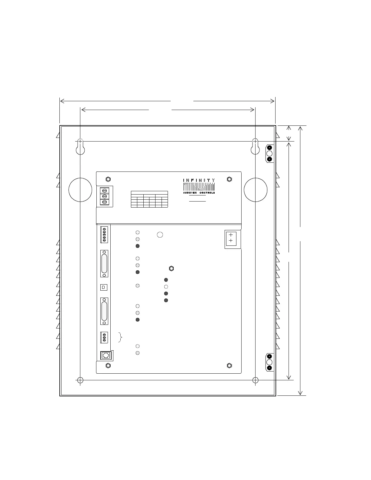
Figure 2 shows the dimensions of the cabinet, provided with the
controller (if purchased), and the location of the mounting screw holes.
Figure 2. Cabinet with Dimensions and Eyelets
for Mounting CMX 240
15.00
12.35
1.33
1.00
19.00
17.00
INFINET
SHLD
–
----
AC INPUT VOLTAGE SELECTION
TO
230V
E3
P2
FROM
24V
TO
E3
P2
FROM
E4
TO
P2
FROM
115V
CMX240
ERROR
SCAN
CPU
+
6V BATTERY
CLEAR
-
+
USE COPPER
CONDUCTORS
ONLY
F2
3A,250V
SLOW BLOW
NEU
HOT
GND
AC
INPUT
E7 E5
E2 E6 E2 E2 E4
E1 E1 E5
MODEM POWER
F5, 2A
THIS DEVICE COMPLIES WITH PART 15 OF
AC POWER
F2
3A,250V
SLOW BLOW
+
-
MEMORY
SHLD
COM
+26V
+26V
RD
TD
RTS
RD
TD
RTS
RD
TD
RD
TD
SERVICE
PORT
THE FCC RULES. OPERATION IS SUBJECT
TO THE FOLLOWING TWO CONDITIONS:
( 1 ) THIS DEVICE MAY NOT CAUSE HARMFUL
INTERFERENCE, AND
( 2 ) THIS DEVICE MUST ACCEPT ANY
INTERFERENCE RECEIVED, INCLUDING
INTERFERENCE THAT MAY CAUSE
UNDESIRED OPERATION.
F6, 1/8A
COMM1
COMM2
CUSTOM
PORT
Technical Manuals Online! - http://www.tech-man.com

 Loading...