CMX 240 Series Installation Guide 19
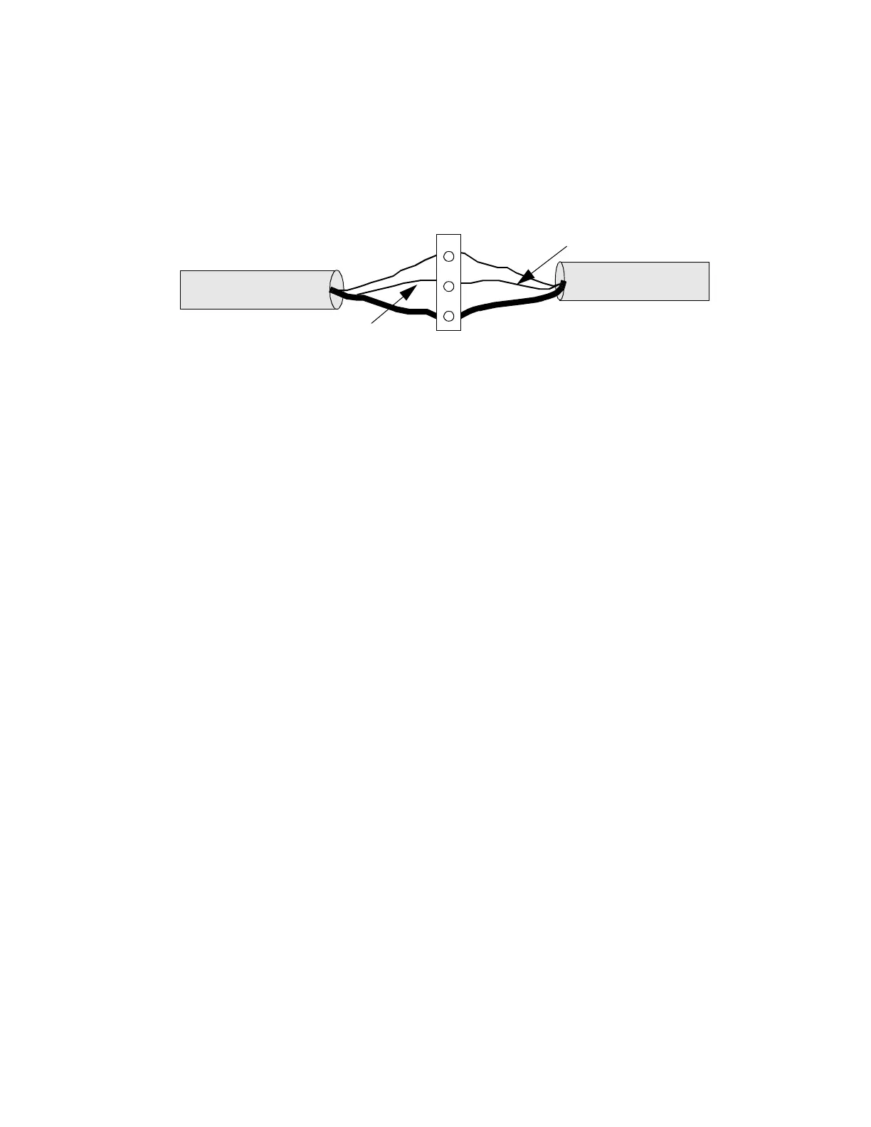
Figure 6 illustrates how to wire the Infinet cable to the removable
terminal block connector on the lower left corner of all CMX 240s.
Figure 6. Infinet Cable Wiring
3. Trim back the shield over the wires.
4. Take the first wire for the incoming Infinet and the first wire for the
outgoing Infinet and slip both in the hole beneath the screw labeled
with a plus sign (top).
5. Tighten the screw down on them until the screw holds the wires in
place.
6. Slip the second (usually black) wire from each Infinet cable under
the screw labeled with a minus sign (middle) and tighten the screw
down on them.
7. Slip the shields from the incoming and outgoing Infinet cables under
the screw labeled SHLD (bottom) and tighten the screw down on
them.
Wiring the TankNet and Probe Power Supply
You connect the TankNet and probe power supply cables to a special
port on the CMX 240 series controller called the CUSTOM PORT.
Figure 7 illustrates how to wire TankNet and probe power supply cables
to the CUSTOM PORT.
+
–
SHLD
Infinet Connection
WHITE
WHITE
BLACK
BLACK
Technical Manuals Online! - http://www.tech-man.com

 Loading...