CMX 240 Series Installation Guide 27
Modem Power Light
On the far left middle of any CMX 240 board there is a light labeled
MODEM POWER. This lights up to indicate the controller is providing
power for the modem. Does not light up when F5 (2A picofuse) is
blown.
System Activity Status Lights
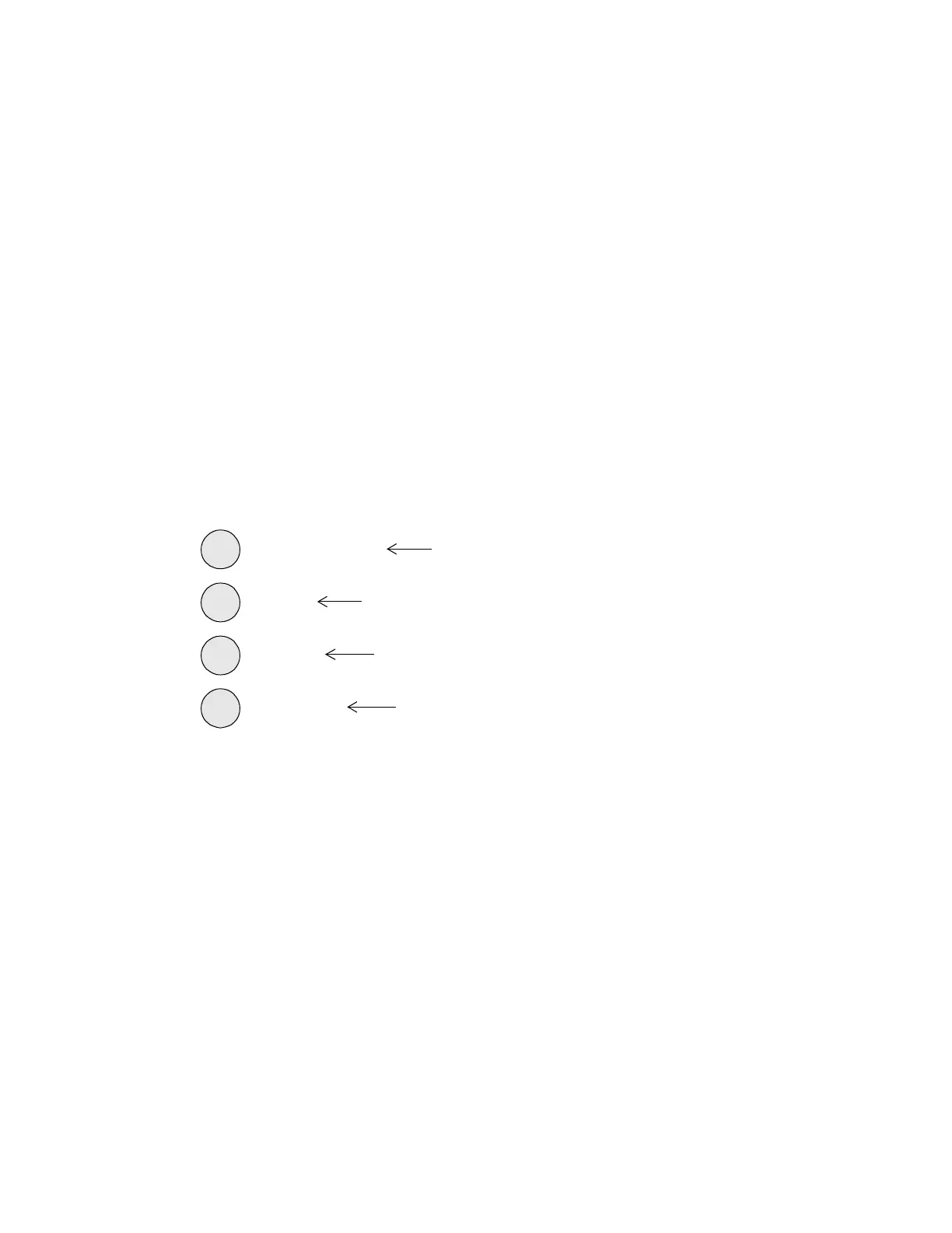
Four system activity status lights are located on the center of the board.
Open the cabinet door and you see a string of green and red lights, some
of them flashing.
Figure 12 shows how the lights appear.
Figure 12. System Activity Status Lights
All these lights, except of course the ERROR light, turn on when the
power comes up. The lights blink to indicate activity. The purposes of
the four lights are as follows:
• AC POWER—Lights up to indicate the AC power is on. Does not
light up when the controller is running on battery backup.
• CPU—Flashes every 0.2 sec that the controller is active.
• SCAN—Flashes once for every scan of the controller.
• ERROR—Lights up if the controller fails the internal integrity
check.
SCAN
AC POWER
CPU
ERROR
(Green)
(Red)
(Red)
(Red)
Technical Manuals Online! - http://www.tech-man.com

 Loading...