20 CMX 240 Series Installation Guide
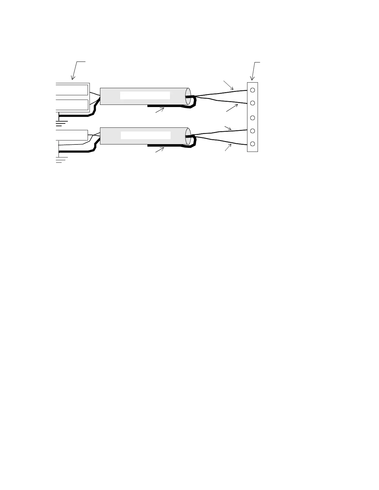
Figure 7. Attaching the TankNet and Probe Power Supply Cables
Wiring TankNet
To connect the TankNet to the CUSTOM PORT use the following
procedure:
1. Trim back the shield over the wires.
2. Slip the positive wire through the hole beneath the screw labeled
with a plus sign.
3. Tighten the screw down on it until the screw holds the wires in place.
4. Slip the negative wire under the screw labeled with a minus sign and
tighten the screw down on the wire.
5. Tie back the shield.
6. Read the following section about safety barriers and then wire them.
Wiring Probe Power Supply
To connect the probe power supply cable to the CUSTOM PORT use
the following procedure:
1. Trim back the shield over the wires.
2. Slip the common wire through the hole beneath the screw labeled
COM.
COM
+26V
Shield
+IN
–IN
Stahl Enclosure
and Safety Barriers
Shield
TankNet Cable
Power Cable
SHLD
Common
Custom Port
Positive Wire
Negative Wire
+26V Wire
Technical Manuals Online! - http://www.tech-man.com

 Loading...