A-2 CMX 240 Series Installation Guide
Table A-1 shows the pinouts for the RS-232 port on the Infinity CMX
240 controller.
Figure A-1 shows the required and optional pinouts for cables
connecting a terminal to the controller, a modem to the controller, and
a modem to the terminal.
a. "To" and "From" are in relation to the Infinity CMX 240 controller.
"Modem" means it is required for the modem.
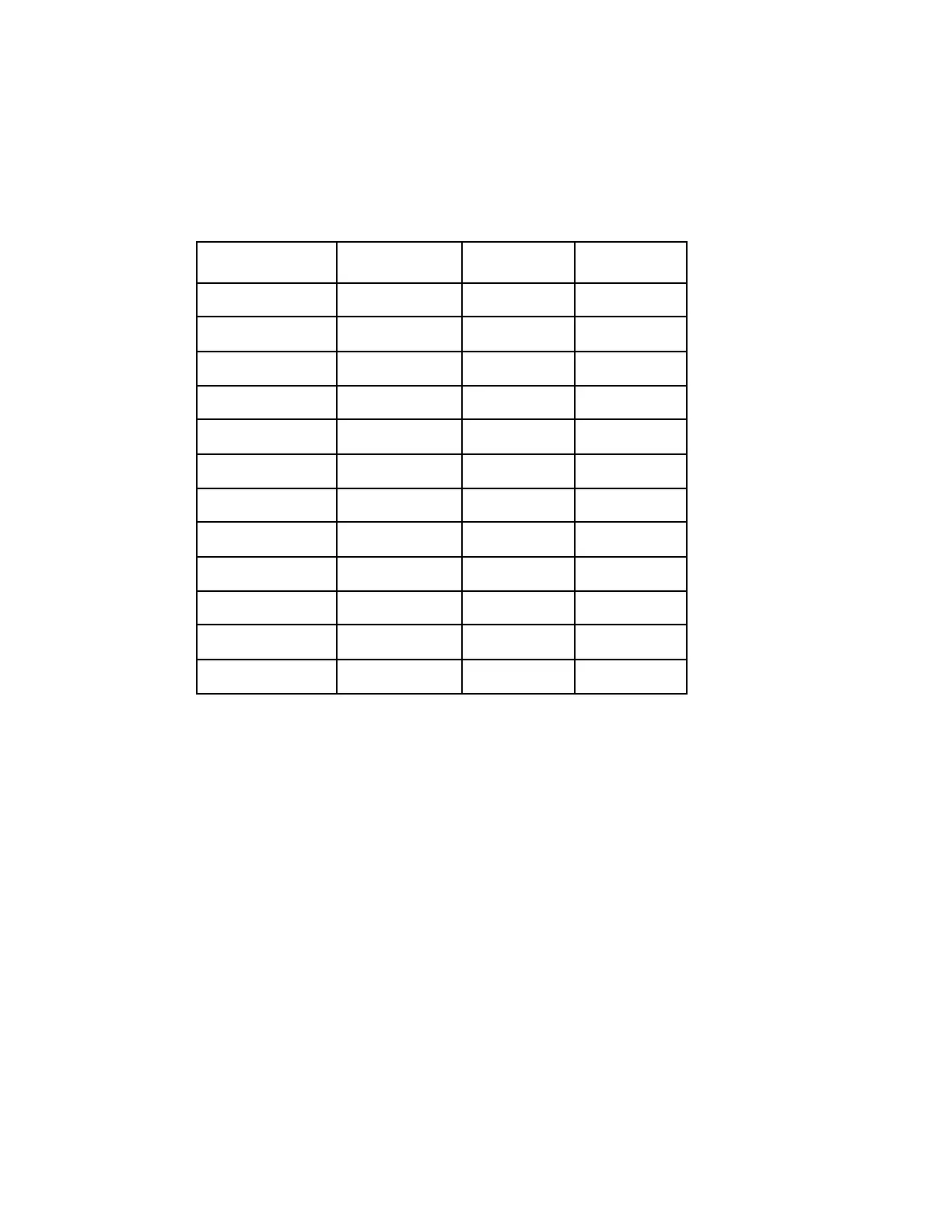
Table A-1. Pinouts for RS-232 Comm Port
a
with Male DB25 Connector to Terminal
Pin Number Purpose Direction Required
1 Chassis --- NO
2TD FromYES
3RD To YES
4RTS FromMODEM
5CTS To MODEM
6DSR To MODEM
7 GND --- YES
8 DCD (CXD) To MODEM
9+V FromNO
10 -V From NO
20 DTR From MODEM
22 RI To NO
Technical Manuals Online! - http://www.tech-man.com
 Loading...
