EasyManuals Logo

Andrew 7.3-Meter ESA User Manual

Default Icon
69 pages
To Next Page IconTo Next Page
To Previous Page IconTo Previous Page
Page #27 background imageLoading...
Page #27 background image
Step 5
Step 6
27
Installation Procedures
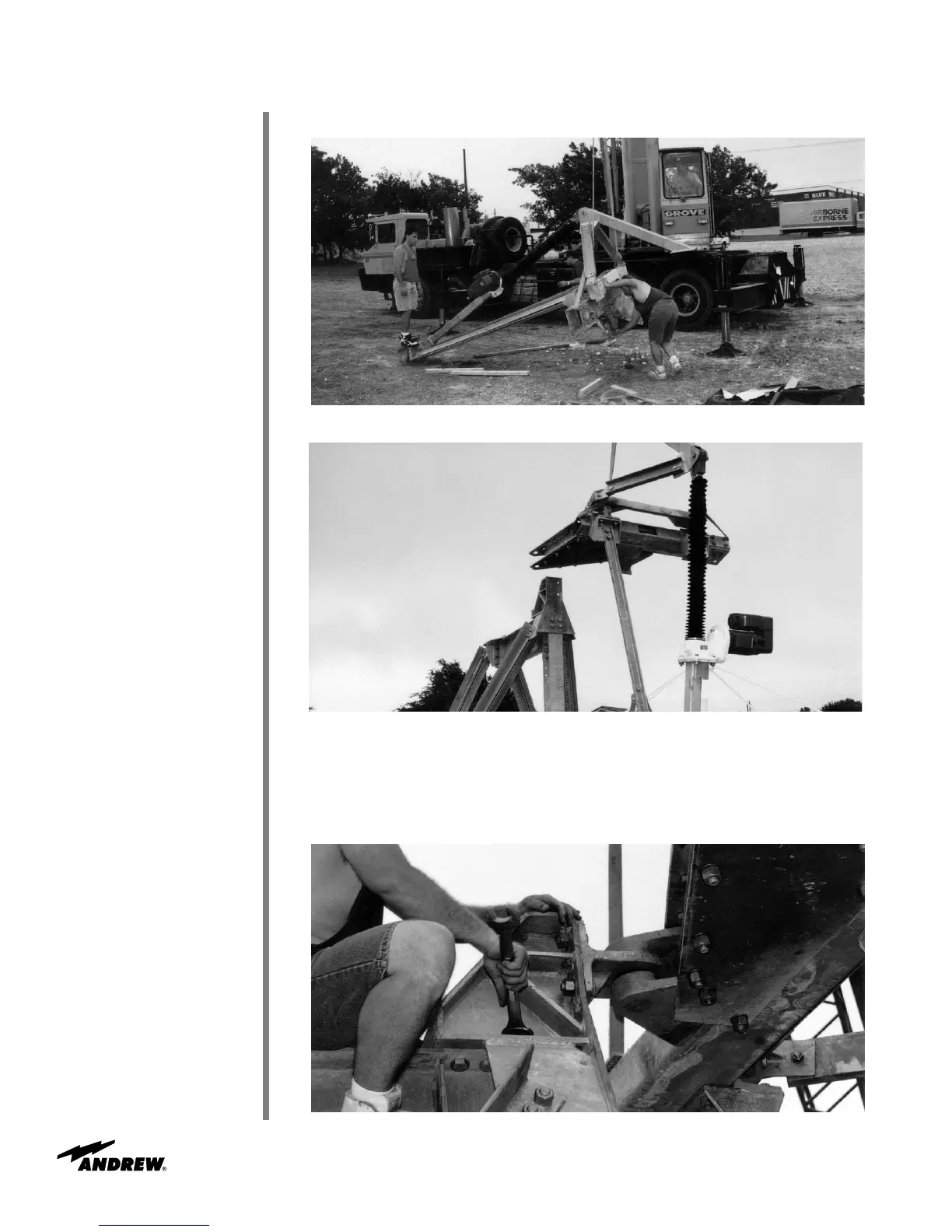
Figure 32B
Apply RTV to flange surfaces and attach 221384 azimuth pivot assembly to 201327A
joint assembly with 7/8 x 2-1/4 hardware from pivot assembly to joint assembly as
shown in Figure 32C. Note: Use one 7/8 by 2-3/4 inch (70 mm) bolt, flat washer and nut
for later attachment of grounding cable.
Figure 32C
Figure 32A
Hoist elevation jackscrew/panning frame assembly to mount as shown in Figures 32A/32B.

Questions and Answers:

Question and Answer IconNeed help?

Do you have a question about the Andrew 7.3-Meter ESA and is the answer not in the manual?

Andrew 7.3-Meter ESA Specifications

General IconGeneral
BrandAndrew
Model7.3-Meter ESA
CategoryAntenna
LanguageEnglish

Related product manuals