Page 43
7. ALARMING AND SUPERVISION
For alarming and supervision, the MRx18 is provided with an alarming interface
represented by three LEDs. Several pieces of information can be queried by the
display without connecting a PC or laptop locally to the MRx18.
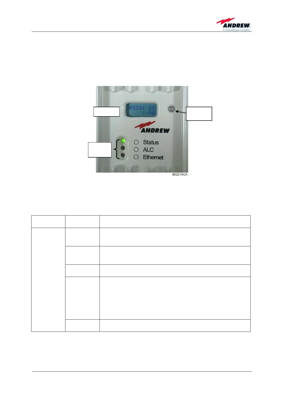
Display
figure 7-1 Display and alarm LEDs, exemplary
7.1. ALARM LEDS
Denotation
of LED
Colour Function/ Indication
Green
A green light indicates the normal operation of the repeater.
Power is present and the current consumption of the unit is
within the specifications.
Orange
An orange light indicates that current consumption of the
repeater is not within defined limits or the LO cannot lock and
the repeater might not work properly.
Off
If the LED is off, the respective MRx18 does not receive any
DC power.
Red
A red light indicates the temperature alarm, which switches to
power-down mode once an over-temperature has been
reached.
The temperature sensor of the controller will continue to check
the temperature in power-down mode. As soon as the
temperature has returned to normal, the controller will enable
the RF-section.
Status
Blinking red/
green
Blinking red/green indicates the antenna alignment assistance
for approx. four minutes.
Reset
Alarm
LEDs