User’s Manual for
MRx18 Rel. 2 Single-Band
Page 44 M0139ADD.doc
Denotation
of LED
Colour Function/ Indication
Off/ red
A red LED indicates that the input power received by the
repeater is too high. The output power of the repeater must be
limited. This will be done by the ALC. Limitation of power
ensures that the final stage is not overdriven and that
intermodulations are kept below the limits.
ALC
Blinking red
The LED is blinking red for four seconds during the boot
process.
Ethernet
Off/ green
The LED is green if the repeater is connected via Ethernet.
LED is blinking during data transfer via Ethernet connection.
table 7-1 Alarm LEDs
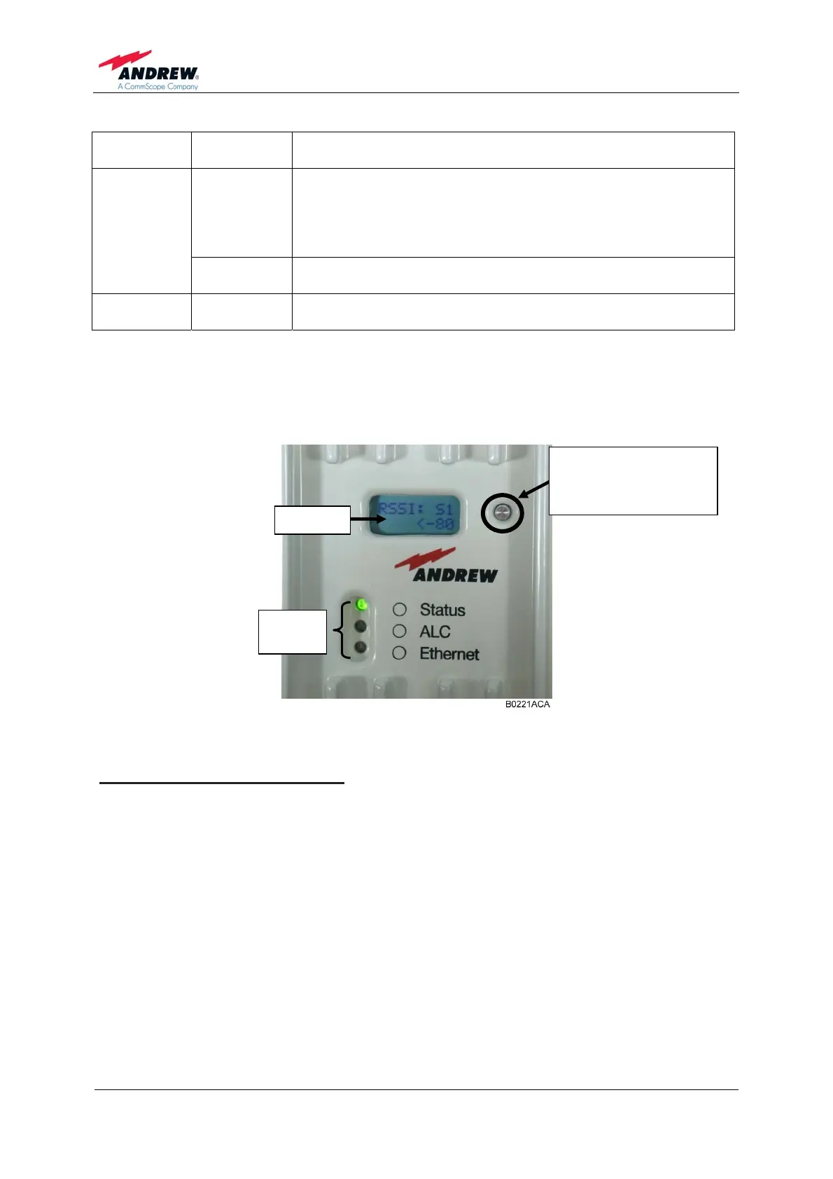
7.2. DISPLAY AND RESET & INSTALLATION ASSISTANCE BUTTON
figure 7-2 Display with reset button and alarm LEDs , exemplary
Functions of the Reset Button:
¾ To align the donor antenna of the MRx18 towards the BTS via the antenna
alignment assistance (as described in chapter 4.2 Electrical Installation), press
the "Reset and installation assistance" switch (illustrated in figure above) for at
least four seconds after (!) the boot process has been finished (i.e. red ALC
LED is blinking for four seconds). This will set the gain to 70 dB and disable
Auto Gain for about four minutes. The status LED will be blinking red/green.
Align the donor antenna towards the BTS/ Node B tower to reach the highest
RSSI level possible. Check the RSSI level at the display (see chapter 7
Alarming and Supervision). After four minutes, the gain and Auto Gain are
adjusted to the same values prior to the activation of the antenna alignment.
Display
Alarm
LEDs
Reset and
installation assistance
button