Page 45
¾ To reset Ethernet settings, username and password to the default factory
settings, press the ‘Reset and installation assistance switch’ during the boot
process (i.e. red ALC LED is blinking for four seconds after power has been
supplied) and keep the switch pressed until the boot process starts again
(Ethernet LED starts blinking). It is not possible to execute a reset when a local
connection is established.
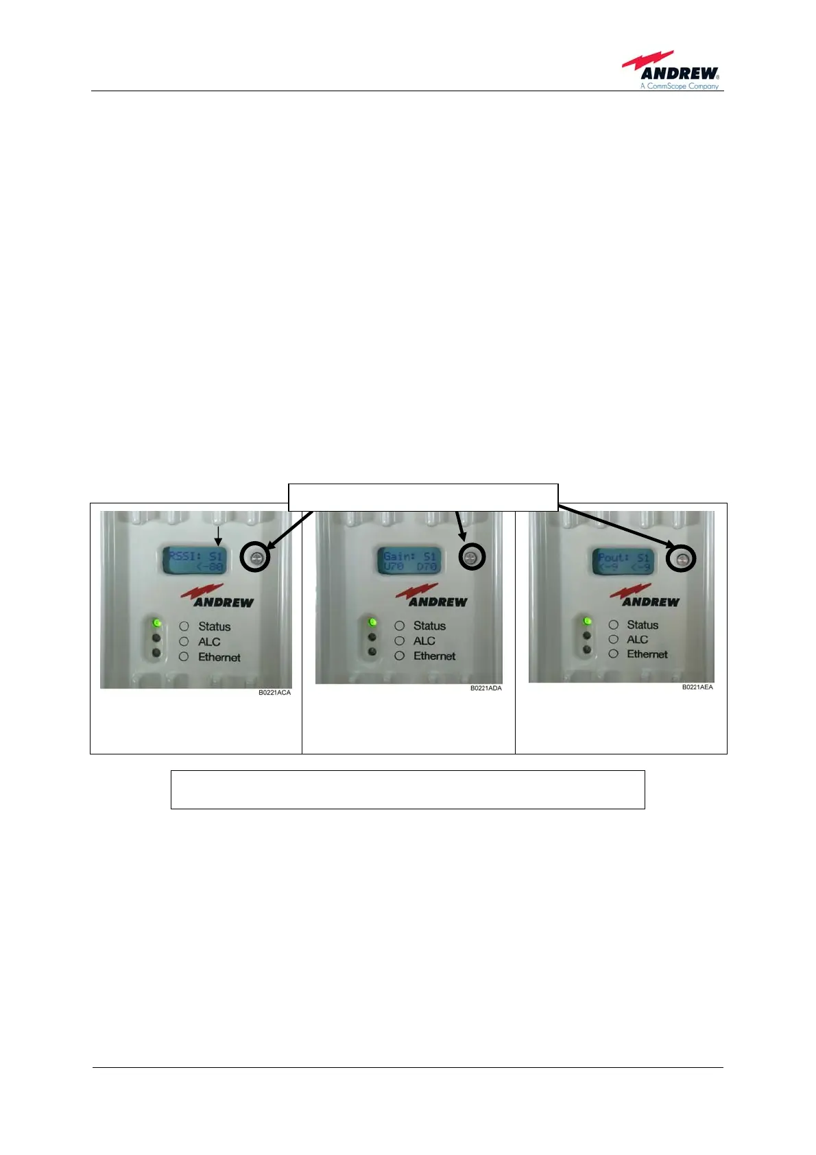
¾ By pushing the reset and installation assistance button (illustrated in figure
above), several pieces of status information of the MRx18 can be queried.
Information given is on RSSI, actual gain UL and DL, actual output power UL
and DL (abbreviated by Pout in the display). In case of more than one segment
equipped, i.e. for dual-band and triple-segment versions, the reset and
installation button is used to switch between the status information with the
sequence as follows:
RSSI of 1
st
segment (S1) Æ RSSI of 2
nd
segment (S2) Æ RSSI of 3
rd
segment
(S3) Æ Gain of 1
st
segment (S1)Æ Gain of 2
nd
segment (S2) Æ Gain of 3
rd
segment (S3) Æ Output power 1
st
segment (S1) Æ Output power 2
nd
segment
(S2) Æ Output power 3
rd
segment (S3)
figure 7-3 Display – RSSI
figure 7-4 Display – Gain
UL and DL
figure 7-5 Display – P
out
UL and DL
Reset and installation assistance button
S1 = first segment
Explanation of display abbreviations above:
S1 = first segment, S2 = second segment; S3 = third segment
In alarm condition the display shows the segment and kind of alarm, when more than
one alarm in different segments is raised the display changes alternately between the
active alarms. When the MRx18 is in normal operation with no active alarms,
"System Ok" is indicated.
) Note: When one segment is switched to "power down" the respective
segment is shown in the display. When several segments are
switched to "power down" the display LED changes alternately
between the segments powered down.