Series SD 39
20
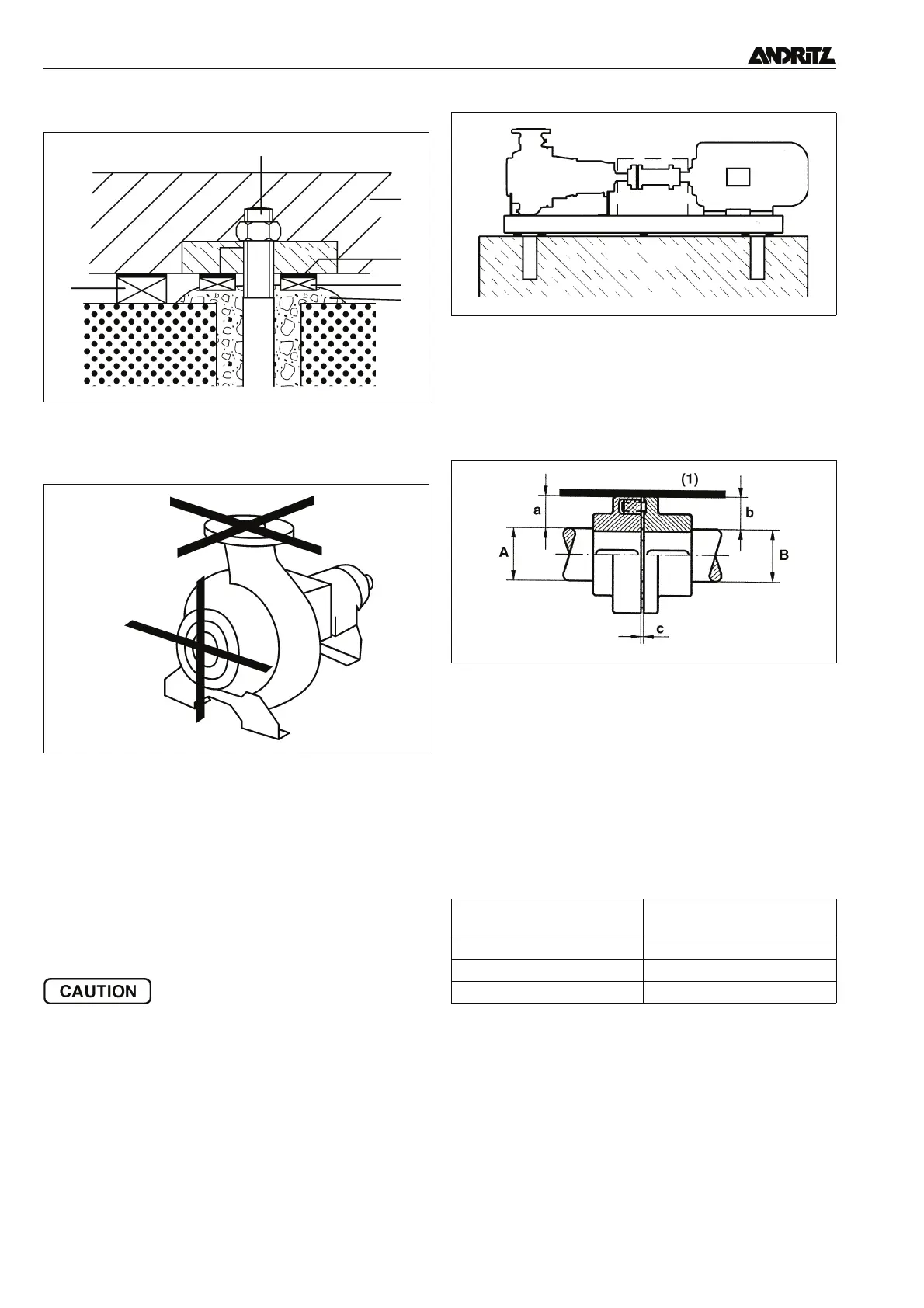
• Place temporary chocks (2) underneath the baseplate (1).
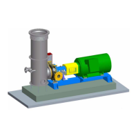
• Check the alignment of pumps on the flange machined sur-
faces using a spirit level. A margin of error of 1 mm in 1 m is
allowed.
• Pour the foundation bolts (3) into place with cement (4) leav-
ing it proud around the bolts (see figure foundation bolts).
• Before the cement sets, insert machined packing pieces (5)
on both sides of each foundation bolt. These pieces should be
attached leaving a minimum distance from the baseplate (1).
• When the cement has set, pack the gap with metal shims of
suitable thickness.
• Remove the temporary chocks (2).
3.3.2 Alignment of flexible couplings (E, H with stub
shaft)
Pump and motor shafts were carefully aligned before delivery.
Displacement can occur during transport thus coupling align
-
ment must be checked before pourring the baseplate.
• Correct vertical misalignment by packing under the base-
plate. For baseplates of up to 1600 mm only place packing in
the drive motor or pump area. Larger baseplates require mul
-
tiple packing.
• Correct lateral misalignment between pump and motor by
slackening the motor fastening bolts, aligning the motor with
the pump and re-tightening.
• Tighten foundation bolts.
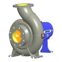
After tightening the foundation bolts, the shaft must be free to
be turned by hand without any tight spots (construction with
packed glands: Packed glands must be slackened for this
test!). Alignment errors may cause premature failing of bear
-
ings or couplings and result in noisy running.
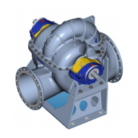
3.3.2.1 Alignment using a straight steel edge
• Place the straight edge (1) axially across the top of the pump
and coupling halves.
• Measure the distances (a) and (b) between the straight edge
and the shafts.
• If the diameter of the pump and motor shaft is equal, then:
a
= b.
• If the diameters differ, then: a + 1/2A = b + 1/2B.
• Repeat the exercise in various positions (displaced by ap-
prox. 90°). The requirements for equal or unequal shaft diam-
eters must be fulfilled in all positions.
• Check the clearance between the coupling halves
(dimension
c). For flexible claw-type couplings this should be:
The distance c must be the same in all positions.
3.3.2.2 Alignment with dial gauges
High rotational speeds and/or spacer type couplings require
more precise alignment using dial gauges.
• Align the coupling halves in both axial and radial directions.
• Maximum permissible axial discrepancy on the coupling face
is 0.05 mm. Preferred value > 0.03 mm. (measure on the out
-
side!).
• Maximum permissible radial discrepancy of coupling periph-
ery is 0.10 mm. Preferred value > 0.05 mm.
Foundation bolts
Pump alignment on the flanges
Correcting vertical alignment
Aligning with a straight steel edge
Coupling Size
(outside diameter)
Distance
c
80-140 mm 2-3 mm
160-225 mm 2-4 mm
250-400 mm 3-6 mm
Table 1: distance between the coupling halves