Series SD 39
22
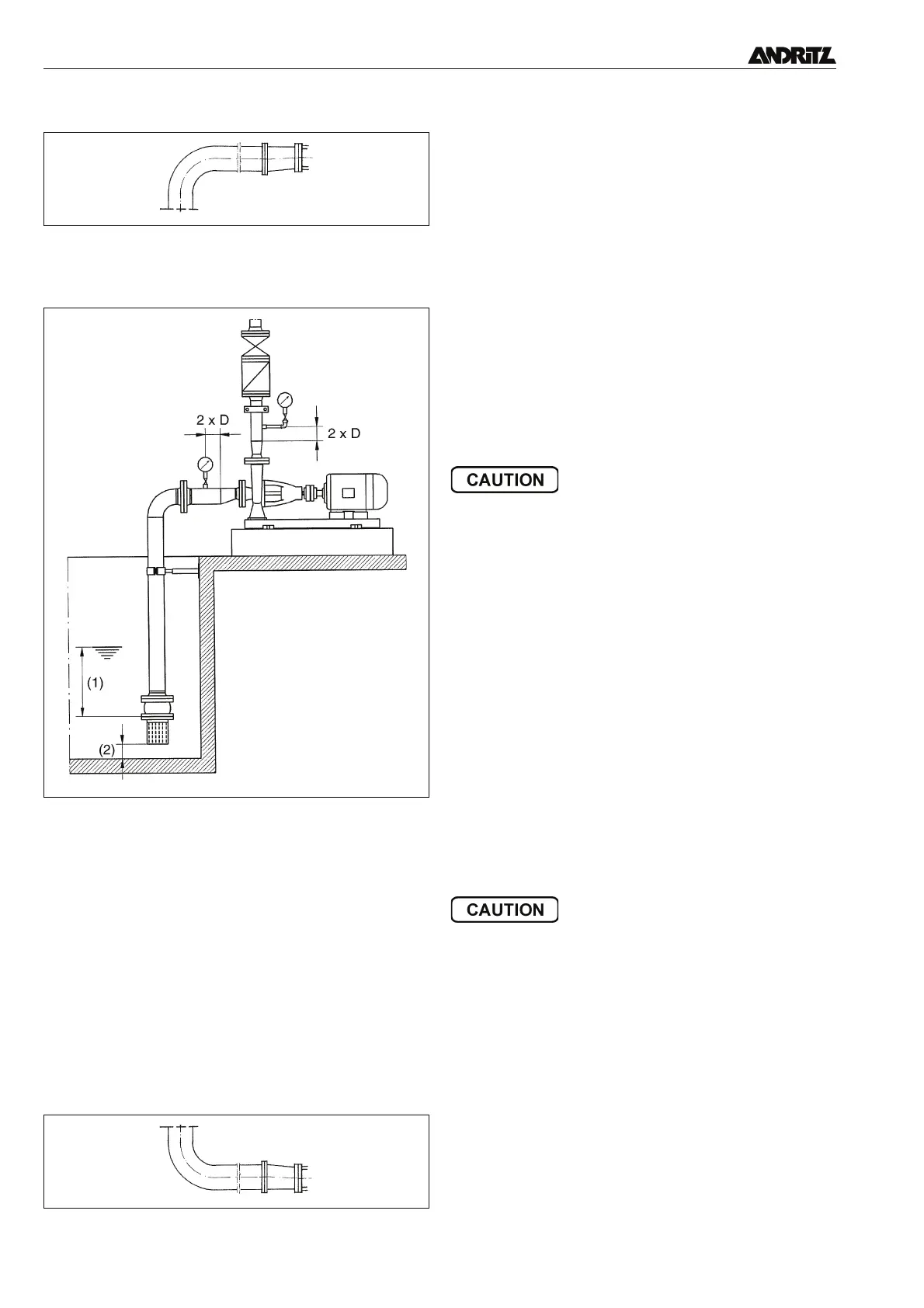
3.4.2 Suction Pipe
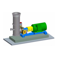
• The maximum flow rate is 2 m/s (when pumping the maxi-
mum capacity).
• Do not fit a row of quarter bends on different levels.
• The pipe should be laid at an inclined angle to the pump (at
least 1 %).
• The pipework must be completely vented and sealed.
• Provide a separate suction pipe for each pump.
• When operating the pump in suction mode without a foot
valve, provide a vacuum installation.
• Ensure that air pockets are not formed in the suction pipe.
• Minimum submergence (1):
Hm = v²/2g+0.1
Hm = minimum submergence
v = flow rate when pumping maximum capacity
g = local gravitational constant = 9.81 m/s²
• The distance from the floor of the container (2) must be at
least half the diameter of the pipe.
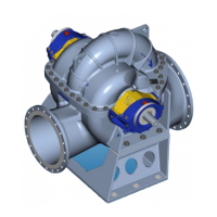
3.4.3 Inlet pipe
• Should be laid as the suction pipe but with the pipe at an an-
gle sloping away from the pump (at least 1 %).
• Fit a return flow stop before the pump.
3.4.4 Discharge pipe
• Lay piping at an angle sloping upwards.
• Maximum flow rate 2.5 m/s (note the fall in meters).
• Ensure that the piping is free of tight spots.
• The pipes must be laid so that the danger of deposits blocking
other pumps is avoided.
• Flange and piping must be designed in accordance with the
maximum pressure.
• Avoid air pockets and vent high points if necessary.
• Differing pipe diameters cause variations in flow rate and
therefore need to be avoided.
• Install a sluice valve and return flow stop in order to prevent
pressure surges at a sudden stop of pump set (for example,
if the set experiences a sudden power loss).
3.4.5 Pressure tests
• Observe the relevant directives.
• Adhere to permitted nominal pressure levels for individual
components.
3.4.6 Auxiliary pipe connections
Sealing and flushing media:
• Connect the pipes.
• Install a regulating valve and a magnet valve (closed without
current).
• Blocking and flushing pressure must be at least 0.5 bar above
the maximum pressure of the pump.
• Set the amounts of blocking and flushing media with the reg-
ulating valve.
Quench media:
• Discharge media without pressure into the quench chamber.
• When using pumps which are fitted with a dual-action me-
chanical seal in tandem arrangement then fit the quench con-
tainer approx. 1.5 m above the mechanical seal.
4. Commissioning and operation
4.1 Commissioning
Before switching on the pump ensure that the following points
have been checked and carried out:
• Check the alignment between pump and motor when operat-
ing horizontal pumps with flexible coupling (see para. 3.3.2).
• Check that the fastening bolts of pump and motor are secure.
• Check that the installation of the pump ensures easy access
to the functional controls.
4.1.1 Bearings
4.1.1.1 Grease lubrication
See para. 5.2.1.1.
4.1.1.2 Oil lubrication
• Delivery with filled bearing housing: Check that the oil level
(1) reaches the middle of the oil level display glass (2). Re
-
move the vent stops (3) if required and top up with oil before
replacing them.
suction pipe
Instructions for laying the suction branch
inlet pipe