Series SD 39
19
ENGLISH
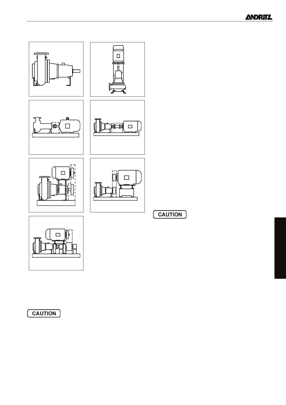
2.2.5 Mounting arrangements
2.3 Dimensions, weights, centres of gravity, capacity
Information on request.
For weights refer to the contract documentation.
2.4 Installation requirements
• Protect motors and pumps from the weather.
• Ensure that the workplace is adequately ventilated/heated/
cooled and observe noise protection requirements.
• Check that access to the pump set (or its components) at the
point of installation is adequate and safe.
Openings must be large enough.
• Adequately rated lifting equipment must be available.
2.4.1 Space required for operation and maintenance
• Ensure that sufficient space is left for subsequent mainte-
nance requirements.
• The set should be easily accessible from all sides.
• The motor cooling fan requires adequate clearance around
the cowl. Ensure that the air inlet and outlet areas are unob
-
structed.
2.4.2 Foundations
• Concrete plinths must be adequately supported in order to
ensure smooth and safe operation.
• Length: At least 100 mm longer than the baseplate.
• Width: The foundation bolts should be at least 100 mm in
front of the edge of the foundation.
• Height: 20-30 mm below final position of underside of base-
plate. If the plinth is to be tiled, make an additional allowance
in order to avoid damaging the tiles should the set have to be
removed.
• The holes in the plinth should be of suitable length for the
foundation bolts used.
• The depth of the foundation should be sufficient to prevent
frost.
• Plinths which rest on a structural floor or ceiling should be in-
tegrated into the original construction using bridging rein-
forcement.
• Foundations should contain sufficient mass in order to damp-
en system vibrations.
• Do not place rubber, cork, feather and/or resilient mats be-
tween baseplate and plinth.
2.4.3 Supply connections
Check that all supplies (power, water etc.) necessary for instal-
lation and later operation are available at the intended pump
position.
3. Mounting/installation
Care and attention to detail during installation are essen-
tial for a trouble-free operation. Incorrect procedures dur-
ing installation may create hazards for personnel or
property or lead to premature failure of the pump.
3.1 Preliminary checks
Check that the dimensions of the plinth/foundation are in ac-
cordance with the drawings.
3.2 Mounting of pump and motor (arrangement A)
See also para. 3.3.
• Common baseplate mounted pump and motor: Adjust the ax-
ial clearance between pump and motor shaft ends.
• Separately mounted pump and motor: Secure the pump onto
the plinth and align it. Then secure the motor and align it with
the pump.
• V-belt drive requires explicit authorisation in our confirmation
of order.
3.3 Installation of assembled pump sets
3.3.1 Horizontal pumps with base plate-mounted drive
motors (E, H, HZ, H with stub shaft)
• Before lowering the set into position clean the plinth surface
and remove any limewash to ensure sound bonding.
• Hang the foundation bolts with nuts in the baseplate fixing
holes.
• Lower the set into position on the plinth surface.