3
Section 2 Preparation Before Use
See Section 2 of the “MG3641A/MG3642A Operation Manual” for the installation environment conditions, the safety
measures, and preparations before the power turning ON.
The preparations for using the Pattern Generator are described here.
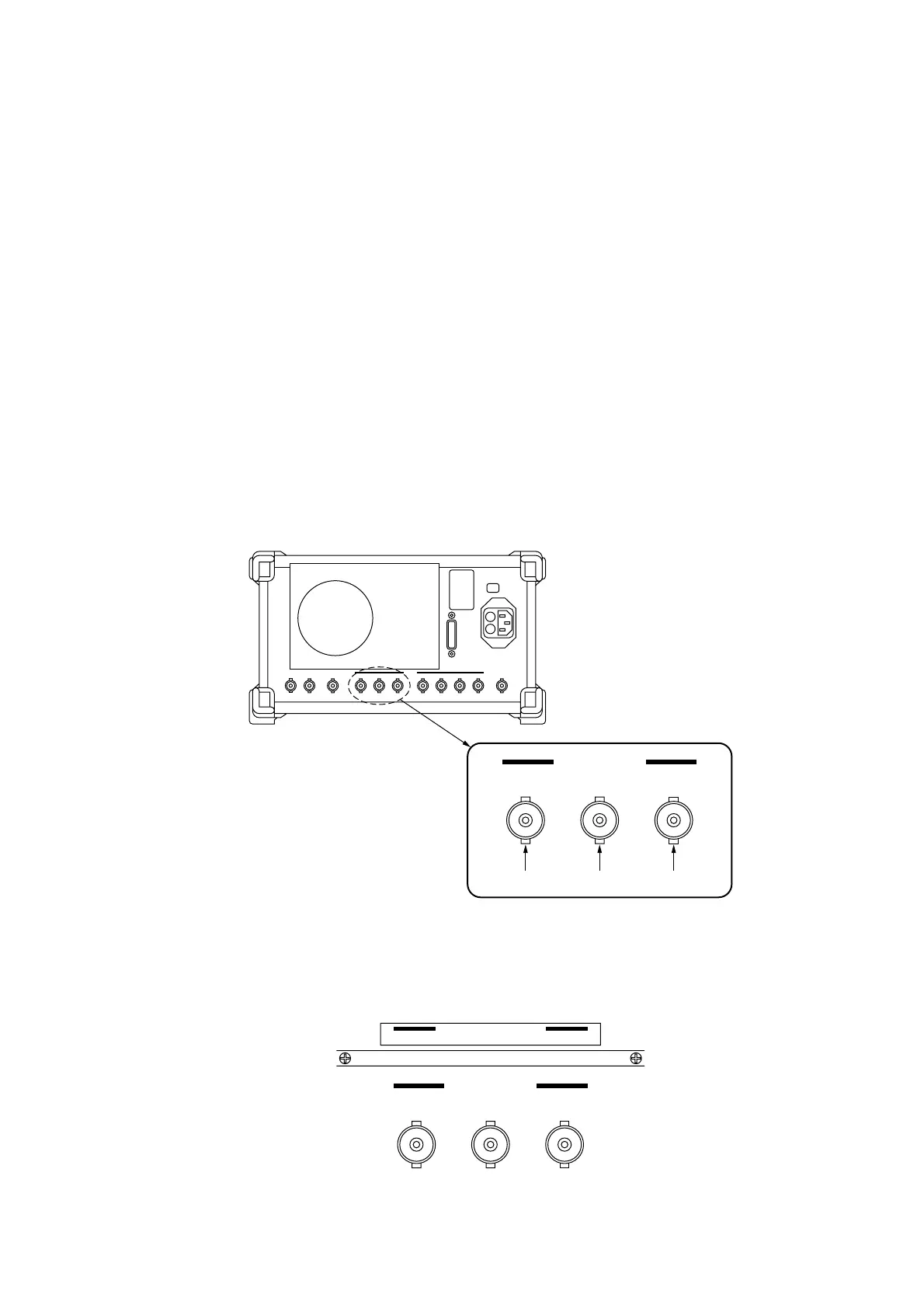
2.1 Data and Clock Connectors Labeling
Pattern Generator outputs data and clock signals by using the Int Mod Cont 1, 2, and 3 connectors on the MG3641A/
MG3642A rear panel. Each connector is allocated as follows:
Int Mod Cont
231
Data 2
1
Data 2
0
Clock
MG3641A/MG3642A Rear Panel
By sticking the attachment labels on near connectors, the erroneous wiring to the connectors can be prevented.
Place the labels above the Int Mod Cont connectors as follows so that they can easily be seen (when the FSK encoder is
implemented, stick its label adjacent to them):
Int Mod Cont
231
Data Pattern Generator
Data2
1
(TTL) Data2
0
(TTL) Clock(TTL)
2.1 Data and Clock Connectors Labeling