22
Section 5 Remote Control by GPIB
5.4 Data Write Details
The writing method of the data generated by Pattern Generator is described in detail.
Since the data is written by the 8-bit byte unit, the dummy data is added to make the data bit length be an integral multiple
of eight. Those dummy data can be 0 or 1 because they can be excluded at the delivery by specifying the data bit length.
Besides, when using the 2-bit NRZ output method, the valid bit length is made to be an even number. When the data bit
length to be written is odd, the bit length is made to be an even number by connecting a couple of data. In this case,
however, even when the delivery mode is set to Single, the data are delivered two times.
Be sure to execute the :PATTern:DATA:DEFined*:ERASE command (* represents a memory number) to erase all the
data from the free pattern memory, before writing data.
Also, when changing written address data, erase all the data from the memory by executing the ERASE command and
then rewrite data from the first address.
Example 1
In case that the following 38-bit data are written into the Defined: 1 free pattern memory and delivered:
“01001101101001011101010010011101101011”
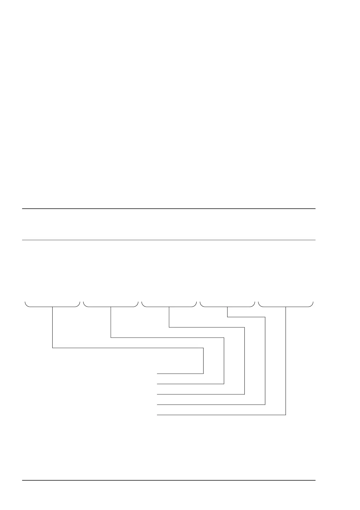
The data are delimited by 8-bit unit and arranged so that LSB becomes the first bit. Dummy data (*: either 0 or 1) are
added to fill the insufficient two-bit end.
01001101101001011101010010011101101011∗∗
: PATTern: DATA: DEFined1: ERASe
: PATTern: DATA: DEFined1 00000, 10110010
: PATTern: DATA: DEFined1 00001, 10100101
: PATTern: DATA: DEFined1 00002, 00101011
: PATTern: DATA: DEFined1 00003, 10111001
: PATTern: DATA: DEFined1 00004,
∗∗
110101
The first bit
↓
After the data are written, the first delivery address is set to “00000” and the data bit length is set to 38 bits before the
delivery.
: PATTern: TOP: DEFined1 00000
: PATTern: LENGth: DEFined1 38