5
• In the case of combined use with FSK Encoder
Since the Pattern Generator data and clock signal output connectors are commonly used for the FSK Encoder data and
clock signal input connectors, the external coaxial cable connection is not necessary.
The Pattern Generator data and clock signal output connectors can be used for the monitor. However, when a long coaxial
cable that is terminated with a low impedance or not correctly terminated, the signals cannot be transferred correctly.
Avoid the signals collision by turning OFF the Pattern Generator output when the FSK modulation is performed by using
the external data generator, etc.
Also read the FSK Encoder Operation Manual as well if FSK modulation is to be performed.
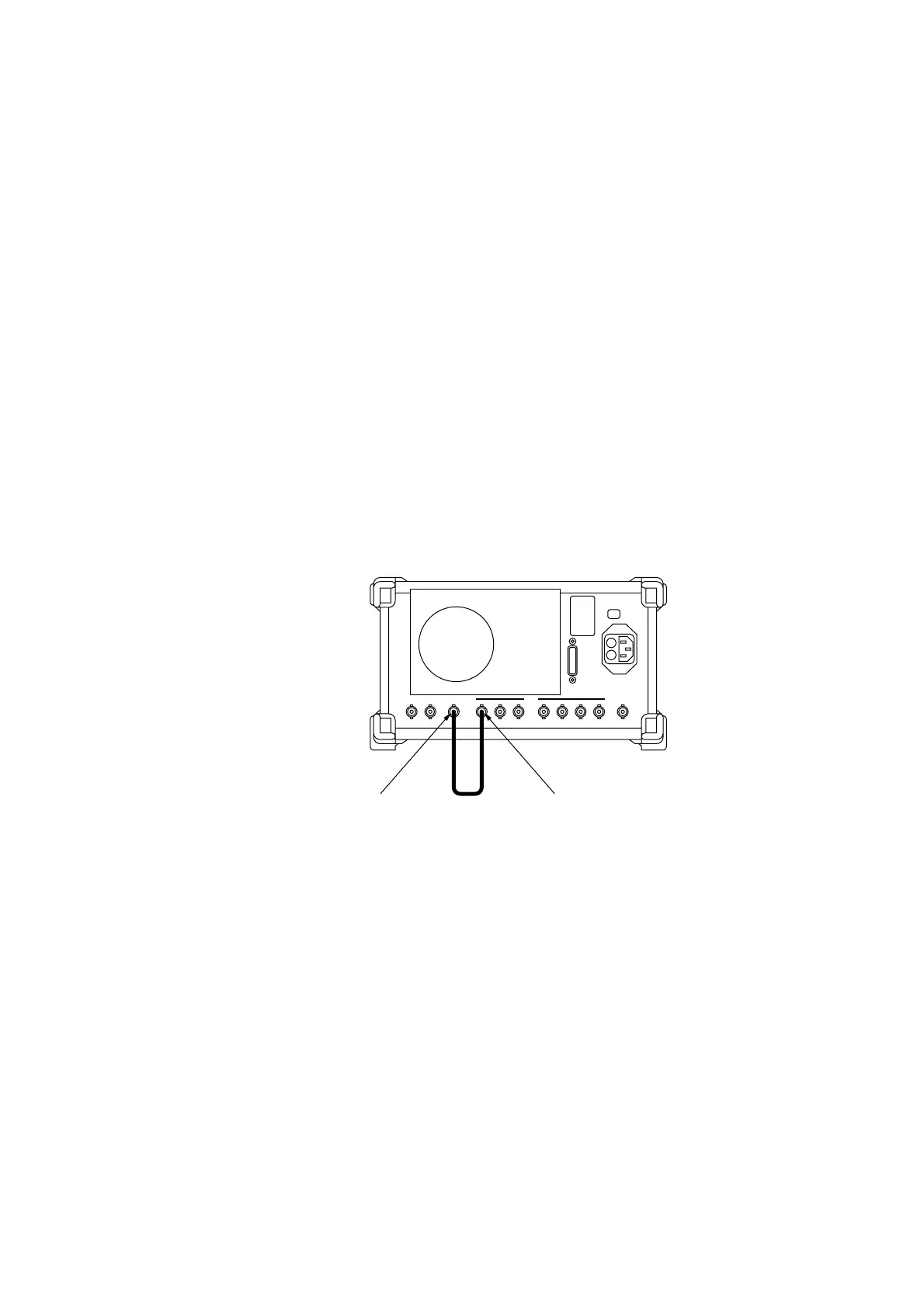
• In case of use as modulated signal source of the pulse modulator
Connect the Int Mod Cont 1 connector allocated as the Pattern Generator data output Data 2
1
to the Pulse Mod Input
connector by using a coaxial cable. Connect them in the shortest distance by using a coaxial cable that is firmly shielded
using for example a double-woven sheath.
In addition, set the pulse modulator input impedance to High (600 Ω).
MG3641A/MG3642A Rear Panel
Pulse Input Data 2
1
Out
Int Mod Cont 1
2.2 Connection