EasyManua.ls Logo

AP TC5-2V2SA - User Manual

AP TC5-2V2SA
60 pages
Print Icon
To Next Page IconTo Next Page
Loading...
TC5-2V2SA
Temperature Controller
USER'S MANUAL
M 890-00170 rev. 05
REV. 01
Question and Answer IconNeed help?

Do you have a question about the AP TC5-2V2SA and is the answer not in the manual?

Overview

The TC5-2V2SA is an electronic temperature controller designed for environmental control in livestock buildings. It allows users to maintain a specified target temperature by managing ventilation and heating equipment. The device supports two stages of variable-speed fans and two optional stages of either constant-speed fans or heating units. One of the constant-speed fan stages can also be configured for mist cooling.

Function Description:

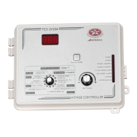
The controller's primary function is to regulate room temperature through precise control of fans and heaters. It features a three-digit display for accurate temperature specification (to within one-tenth of a degree Fahrenheit or Celsius). Pilot lights indicate the operational status of outputs, allowing for remote monitoring.

Important Technical Specifications:

  • Supply: 115/230 VAC (-18%, +8%), 60Hz (TC5-2V2SA) or 50Hz (T55-2V2SA). L1 same phases as Stage 1 and 2. Overload and overvoltage protection fuse F11-1A fast blow.
  • Back-up Supply: 12 VDC for AC back-up, capable of activating stages 3 and 4 if supplied with DC back-up voltage.
  • Stage 1 (Variable Output): 60 Hz, 10A FAN (1/2 HP/115 VAC) / (1.5 HP/230VAC), fuse F1-15A slow blow.
  • Stage 2 (Variable Output): 60 Hz, 10A FAN (1/2 HP/115 VAC) / (1.5 HP/230VAC), fuse F8-15A slow blow.
  • Stage 3 (ON-OFF Output): 115/230 VAC, 60 Hz, 30VDC, 6A FAN, 10A RES, heating or cooling, fuse F3-15A slow blow.
  • Stage 4 (ON-OFF Output): 115/230 VAC, 60 Hz, 30VDC, 6A FAN, 10A RES, heating or cooling, fuse F4-15A slow blow.
  • Alarm (ON-OFF Output): 115/230 VAC, 60 Hz, 30VDC, 3A, fuse F7-3A slow blow.
  • Probes: Low voltage (< 5V), isolated from the supply. Operating range: -40.0° to 120.0°F (-40.0° to 48.9°C). Accuracy: 1.8°F (1°C) between 41° and 95°F (5° and 35°C). Up to four independent temperature probe inputs are supported for more accurate average room temperature readings and faster reaction times.
  • Enclosure: ABS, moisture and dust-tight.
  • Operating Environment: The room temperature where the controller is located must always remain between 32°F and 104°F (0°C to 40°C). Installation in a corridor is preferable to avoid harmful gases or excessive humidity.

Usage Features:

  • Temperature Settings:
    • Units: Temperatures can be displayed in either Celsius or Fahrenheit, selectable via an internal switch.
    • Viewing Temperatures: Users can view the average room temperature or individual probe temperatures. Minimum and maximum recorded temperatures (since the last reset) are also viewable for both average room temperature and individual probes.
    • Set Point Adjustment: The target room temperature (set point) can be adjusted between -40.0°F and 99.9°F (-40.0°C and 37.7°C).
    • Temperature Curve: The controller supports a temperature curve feature, allowing the set point to automatically change over a defined period (up to six points, 99 days maximum). This is useful for managing temperature changes as animals grow.
  • Ventilation Settings:
    • Cooling Operation: The controller manages variable-speed fans (Stage 1 and 2) and constant-speed fans (Stage 3 and 4) based on temperature differentials and bandwidths.
    • Minimum Ventilation Cycle: When cooling is not required, Stage 1 fans can operate continuously or intermittently at a minimum speed to reduce humidity and supply oxygen. The cycle (time on/time off) is adjustable.
    • Humidity Compensation: Stage 1 minimum speed can automatically increase proportionally with rising relative humidity above a set point. If humidity compensation is active and relative humidity exceeds the set point, minimum ventilation fans operate continuously.
    • Minimum Ventilation Speed Curve: Similar to the temperature curve, this feature allows Stage 1 minimum speed to automatically adjust over time (up to six points, 99 days maximum).
    • Differentials: Adjustable temperature differences for fan stages to turn on/off.
    • Full-Speed Fan Start-up: Variable speed fans receive maximum voltage for 2 seconds at start-up to overcome inertia and de-ice blades.
    • De-icing Cycle: A de-icing cycle for Stage 2 variable-speed fans in cold weather conditions is provided, with adjustable cycle time and de-icing duration.
  • Heating Settings:
    • Heating/Cooling Option: Stages 3 and 4 can be configured for either heating or cooling via internal switches.
    • Zoned or Cascading Heaters: The controller supports both cascading (sequential operation) and zoned heating (independent operation based on specific probes). Zoned heating includes a protection mechanism to prevent ventilation problems when temperature differences between zones are significant.
    • Heater Offsets and Differentials: Adjustable temperature differences for heaters to turn on/off relative to the set point.
  • Mist Cooling:
    • The last cooling stage can be configured as a mist stage.
    • Mist units operate on a timer cycle (time on/time off) and can be turned off if humidity reaches a user-defined maximum level (if humidity compensation is activated).
    • Adjustable mist differential and offset.
  • Alarm Settings: High/low temperature alarm offsets are adjustable from 0.5°F to 40°F. The alarm activates for power failure, supply circuit fault, or high/low temperature.
  • Test Mode: Allows simulation of temperature changes to verify controller performance without actual environmental changes.
  • Parameter Locking: Settings can be locked to prevent accidental modifications.
  • Computer Control: The controller can be connected to a computer for centralized management and diversified control strategies.
  • Control of Air Inlet Movement: When used with a PF-5B controller, air inlet movement can be coordinated with fan operation.

Maintenance Features:

  • Overload and Overvoltage Protection: Fuses are installed at the input and outputs to protect circuitry.
  • Troubleshooting Guide: The manual provides solutions for common issues such as display malfunctions, defective probes, erratic fan operation, and heating unit problems.
  • Probe Management: Up to four temperature probes can be connected, and individual probes can be activated/deactivated. The controller can identify defective probes. Probe cables should be shielded and isolated from high voltage sources.

AP TC5-2V2SA Specifications

General IconGeneral
BrandAP
ModelTC5-2V2SA
CategoryTemperature Controller
LanguageEnglish