User Manual Smart-UPS RC XLI/XLICH/XLI-CC 1000/2000/3000 VA 220/230/240 Vac Tower/Rack-Mount 4U 7
Output hardwire instructions
Adhere to all national and local electrical codes.
Wiring must be performed by a qualified electrician.
• Use 1.3 mm
2
(#16 AWG) wire (not supplied)
• Maximum output rating: 220-240 V, 50-60 Hz, 10 A
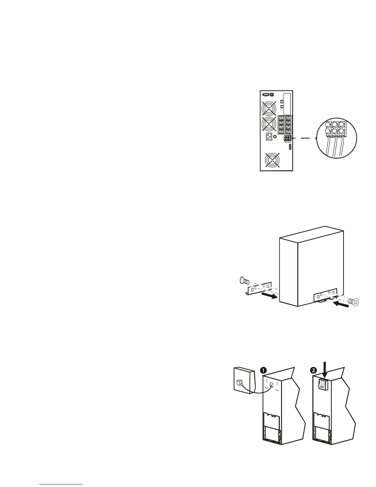
1. Locate the hardwire terminal block cover on rear panel of UPS.
Remove the screw securing the cover and remove cover.
2. Connect wires to terminal block. Terminals are labelled for proper
wire configuration.
3. Replace and secure cover removed in step 1.
Tower configuration
Install stabilizer brackets
1. Stabilizer brackets must be installed on tower units.
2. Each bracket must be secured with two flat head screws
(supplied).
NOTE: Screws are pre-installed on left side of unit. These
screws must be removed from unit and used to secure
stabilizer bracket. Screws for securing stabilizer bracket
to right side of unit are included in hardware bag
supplied with unit.
Install display panel
Locate UPS display panel in UPS packaging.
su0227a
su212a
su0228a