Apeks Supercritical The Duplex™ Operation Manual
8
Revision Date 8/28/2018
a black handle that can be opened in order to bypass the OPV. This is done during
priming of the compressor and during head maintenance. (see appendix B)
2.1.1.4. Junction Box – The diaphragm compressor has a single junction box for the pressure
switches that has a Harding Connector (electrical quick-connect) and thermocouples that
go to the main control enclosure.
2.1.1.5. Regenerative Heat Exchangers – There are two regenerative heat exchangers that are
located on the pump, one for each diaphragm head. These heat exchangers remove heat
from the compressed CO
2
to use on the separators.
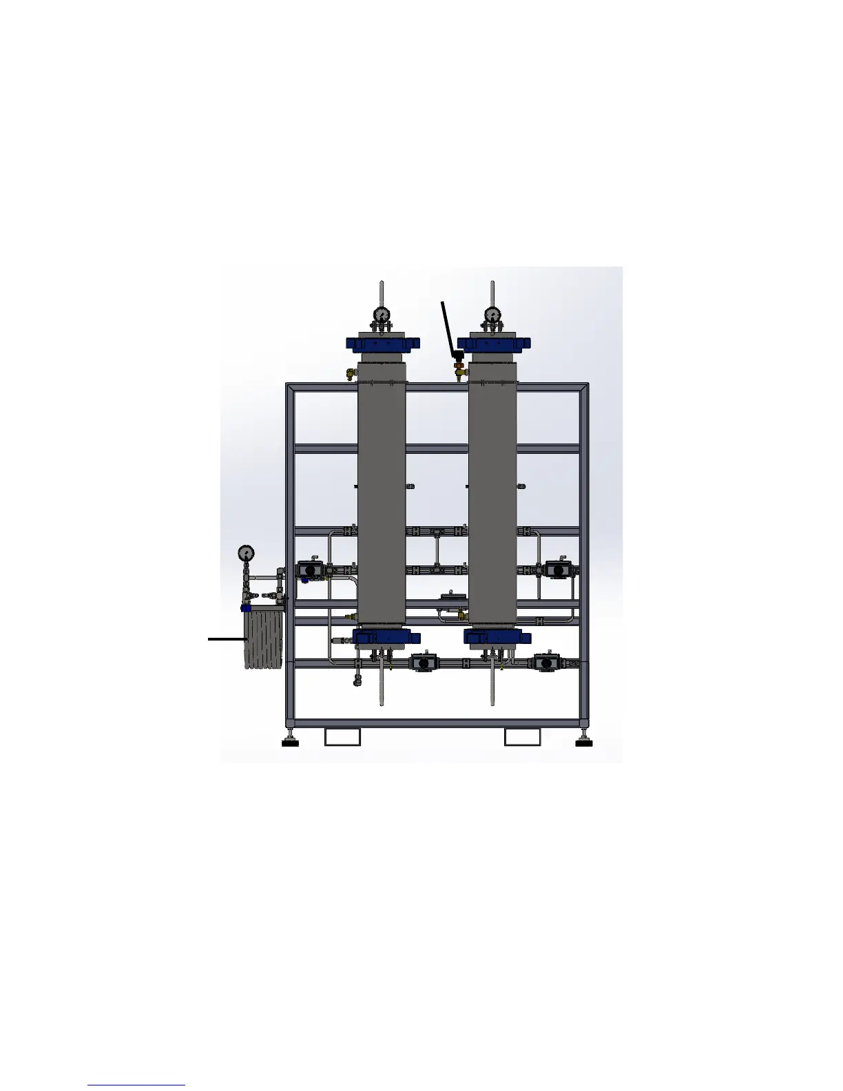
2.1.2. Extraction Vessel Stand
2.1.2.1. Extraction Vessels – There are two extraction vessels on each stand. Vessel A is
located on the right-hand side of the stand and Vessel B is located on the left. These
vessels can be either 5L or 20L and are Hammer Union Closure vessels. This closer
mechanism uses a nut to hold down a cap to allow the vessel to pressurize. Seals on this
vessel are cup style seals which expand with the presence of pressure and create a face
seal on the vessel. Extraction vessels are loaded and unloaded from the top of the
vessel. When loading, unloading and cleaning these vessels be sure to keep face surface
and threads clean. Failure to keep these surfaces clean can cause your vessel not to
seal properly and could cause damage to your cup seal.
2.1.2.2. Locking Vessel Isolation Valves – Each extractor has two locking isolation valves that
should be utilized whenever the operator is working in any vessel. These valves are
A
B
Control Heat
Exchanger