27
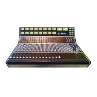
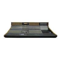
4.1 Summing Bus Sub-masters
The Summing Bus Sub-masters (labeled SUB 1-8) are the final stage before the Summing Bus
outputs are fed to the BUS OUTPUT 1-8 (ACA OUTPUT) sub-D connector on the rear panel. The
output of the Summing Bus Sub-masters (SUB 1-8) can also be routed to the Program Bus via
individual Left and Right assignment buttons.
The controls for each 168B Summing Bus Sub-master (SUB 1-8) function as follows:
NOTE: Sub-masters assigned to the Program Bus will mute if the console is in Solo-In-Place
and a channel or Echo Return is soloed.
SOLO: Activates the PFL or AFL Solo function
• Illuminates when engaged
ON: On/off switch for the Summing Bus Sub-master (SUB 1-8)
• Illuminates in when engaged
• Provides max kill in “off” position with TRIM fully clockwise (this is the calibrated
position of the Send)
TRIM: Serves as a 0dB to -84dB trim control for the Bus Out application or 0dB to -30dB trim
control for Return to Program Bus
• Cut only (calibrate level to infinite cut)
CAL (trim-pot): The trim-pot calibrates the output of the Active Combining Amplifier
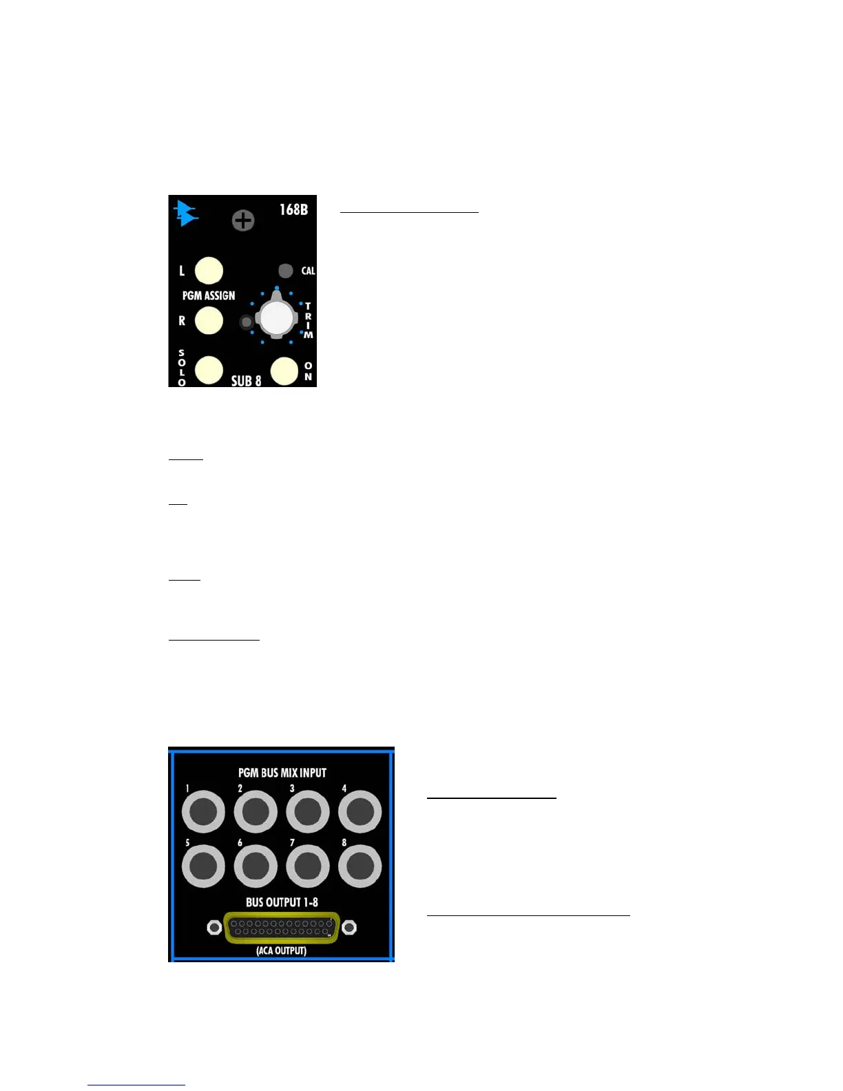
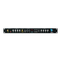
4.2 168B Connections
The rear panel connections for the 168B Summing Bus Sub-master module are as follows:
L and R PGM ASSIGN: Individual assignment of the Summing Bus
(ACA) output to the Left and Right Program Buses
• The Left and Right Program Bus Assignment switches are
actually fed from the PGM BUS MIX INPUT jacks on the rear
panel
o These jacks are normalled to the output of the
Summing Buses (ACA), but break that connection when
a jack is inserted
o The normal or inserted signal present at the PGM BUS
MIX INPUT jack feeds the Left and Right Program
(PGM) Bus Assignment switches
• Illuminates when engaged
PGM BUS MIX INPUT:
• Balanced, Line-level
• 1/4” tip-ring-sleeve jack
• Replaces the Summing Bus output signal at the
Left and Right Program Assignment switches
when a jack is inserted
BUS OUTPUT 1-8 (ACA OUTPUT):
• Balanced, Line-level
• Female 25-Pin Sub-D connector