31
5.4 268B Connections
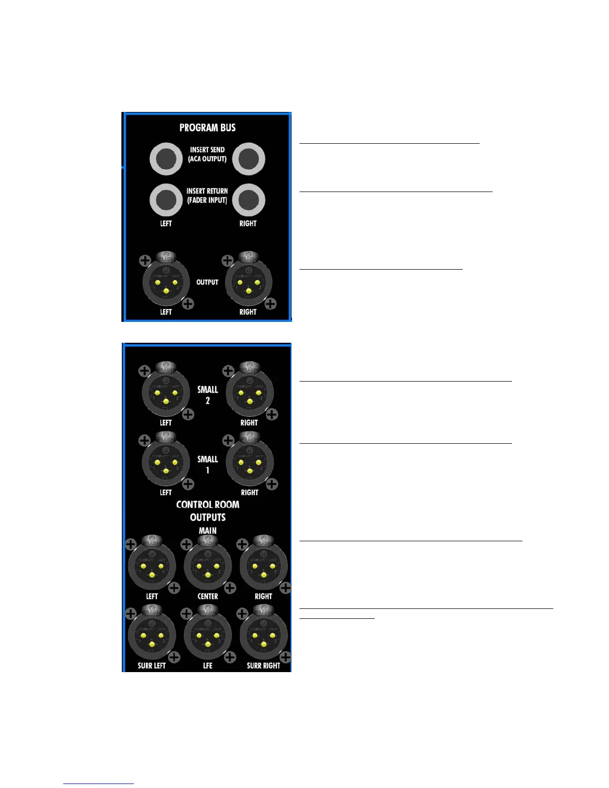
The rear panel connections for the 268B Program Bus Output Master and Monitor Output
module are as follows:
PROGRAM BUS INSERT SEND (ACA OUTPUT):
• Balanced, Line-level
• 1/4” tip-ring-sleeve jack
• Half-normalled to Program Insert Return
PROGRAM BUS INSERT RETURN (FADER INPUT):
• Balanced, Line-level
• 1/4” tip-ring-sleeve jack
• Replaces the Program Insert Send signal when a jack is
inserted and the PRG INS button is engaged
PROGRAM BUS OUTPUT LEFT and RIGHT:
• Balanced, Line-level
• Male XLR
SMALL 2 CONTROL ROOM OUTPUTS LEFT and RIGHT:
• Balanced, Line-level
• Male XLR
SMALL 1 CONTROL ROOM OUTPUTS LEFT and RIGHT:
• Balanced, Line-level
• Male XLR
MAIN CONTROL ROOM OUTPUTS LEFT, CENTER, RIGHT:
• Balanced, Line-level
• Male XLR
MAIN CONTROL ROOM OUTPUTS LEFT SURROUND, CENTER,
RIGHT SURROUND:
• Balanced, Line-level
• Male XLR