46
9.3 168B Summing Bus Sub-master (ACA) Connections
The rear panel connections for the 168B Summing Bus Sub-master module are as follows:
9.4 268B Program Bus/Master Output Connections
The rear panel connections for the 268B Program Bus/Master Outputs are as follows:
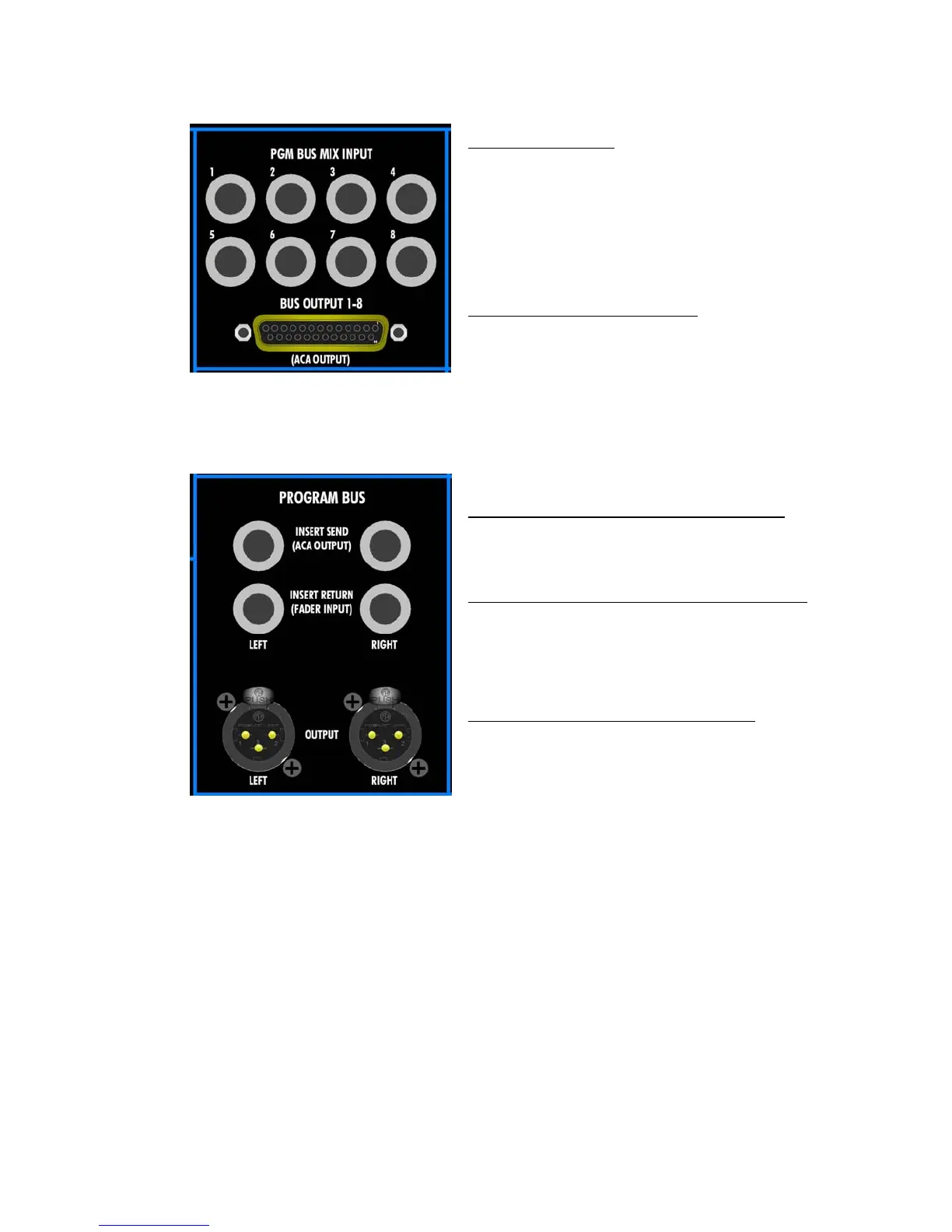
PGM BUS MIX INPUT:
• Feeds the inputs to the Program Bus
Assignment switches on the Summing Bus Sub-
masters 1-8
• Balanced, Line-level
• 1/4” tip-ring-sleeve jack
• Replaces the Summing Bus output signal at the
Left and Right Program Assignment switches
when a jack is inserted
BUS OUTPUT 1-8 (ACA OUTPUT):
• Output from the Summing Bus Sub-masters
SUB 1-8
• Balanced, Line-level
• Female 25-Pin Sub-D connector
PROGRAM BUS INSERT SEND (ACA OUTPUT):
• Balanced, Line-level
• 1/4” tip-ring-sleeve jack
• Half-normalled to Program Insert Return
PROGRAM BUS INSERT RETURN (FADER INPUT):
• Balanced, Line-level
• 1/4” tip-ring-sleeve jack
• Replaces the Program Insert Send signal when a
jack is inserted and the PRG INS button is
engaged
PROGRAM BUS OUTPUT LEFT and RIGHT:
• Fed post the Stereo Master Fader
• Balanced, Line-level
• Male XLR