Page 33
Electrical Connections
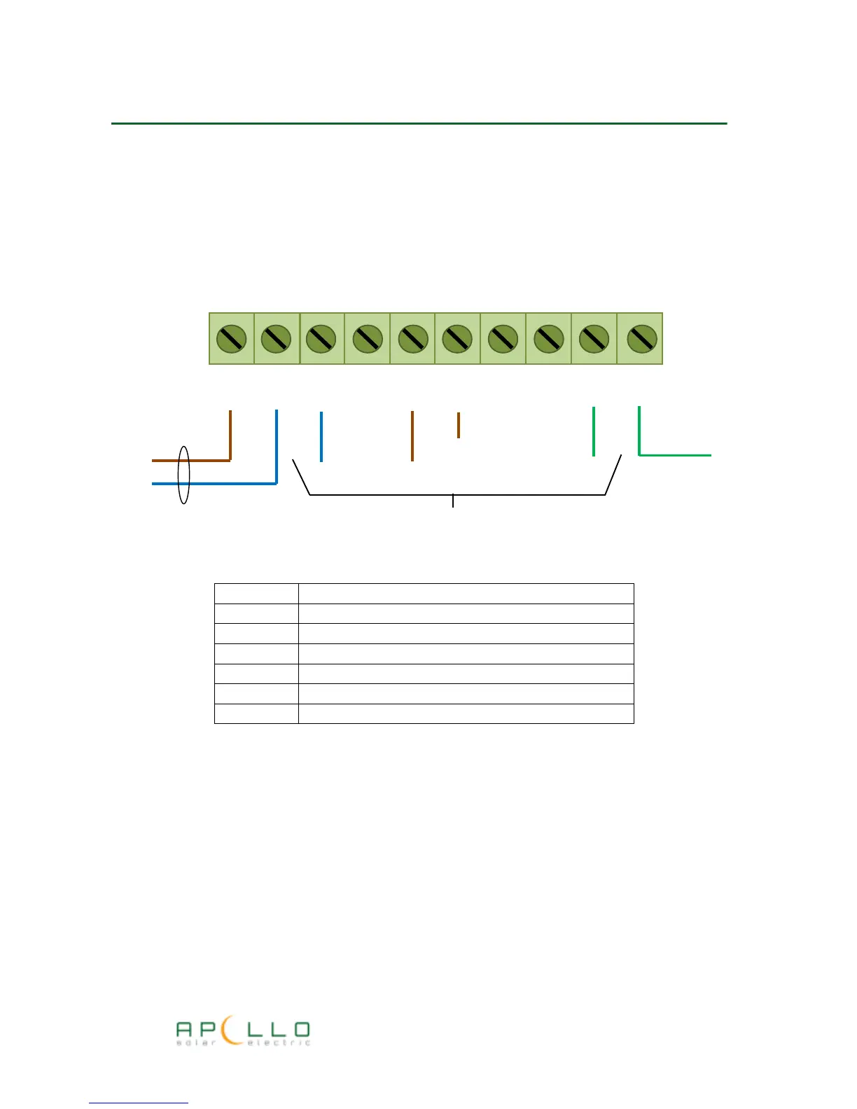
All electrical connections are made to the unit via a screw terminal block located under the front
cover as shown:
Current sensor clamp connection
The current sensor is supplied with a 2-pin connector and is plugged into the two pin socket
marked “CT CLAMP” on the main Apollo GEM circuit board.
For wireless systems the CT clamp input is not used.
Temperature Sensor Connection
If used, the temperature sensor is plugged into a 4-pin RJ11 connector situated at the front of the
main Apollo GEM circuit board marked “TEMP SENS”
TERMINAL
CONNECTION
L Supply live from isolator switch
N Supply neutral and Heater neutral
L1 Electric Water Element Live (Heater 1)
L2 Electric Water Element Live (Heater 2)
L3 Not used in standard installation
E Supply earth and electric water element earth
N
L N N N L1 L2
E E E
Electric water element Cable
Supply Cable
Supply Earth
L