SW Version 2.04 30-January-2009 Page 34 of 128
NO LINK ALARM on
data interface
The NO LINK alarm will be raised if the GigaBit IP input
module detects no link over a period of 1 second.
Possible causes for the alarm are link loss or no-lock on
input card.
NO SIGNAL ALARM on
data interface
The NO SIGNAL alarm will be raised if the GBIP input
card detects no bit rate on all the configured IP inputs
over a period of 1 second.
Note:
These alarms and the switching hysteresis are not configurable
When an alarm leading to a switch has been triggered on the main card, all
routed streams are switched from the main module to the spare module. The
switch will be effectuated even if an alarm is active on the spare card.
MMI functionality remains on the same card after a switch
Switching can be done manually from GUI
There is no automatic switching from spare to main module if/when alarms are
cleared. This must be done manually.
Alarms which are filtered through the alarm filter GUI will not trigger source
switching.
MMI
Input redundancy does not affect MMI functionality. If the main input module is
configured as supporting the Man Machine Interface (MMI), this configuration will
remain even though all input sources are switched from Main to Backup card. It is for
that reason that there is always a mirror configuration on both cards.
Before implementing redundancy
Before configuring input redundancy, it is necessary to configure the main IP input
module. This is done through the Inputs->IP tab in the navigation pane. The
configuration of the main input module will then automatically be mirrored to the
redundant IP input module in the redundancy configuration – the operator need not
do any manual configuration of the redundant IP card.
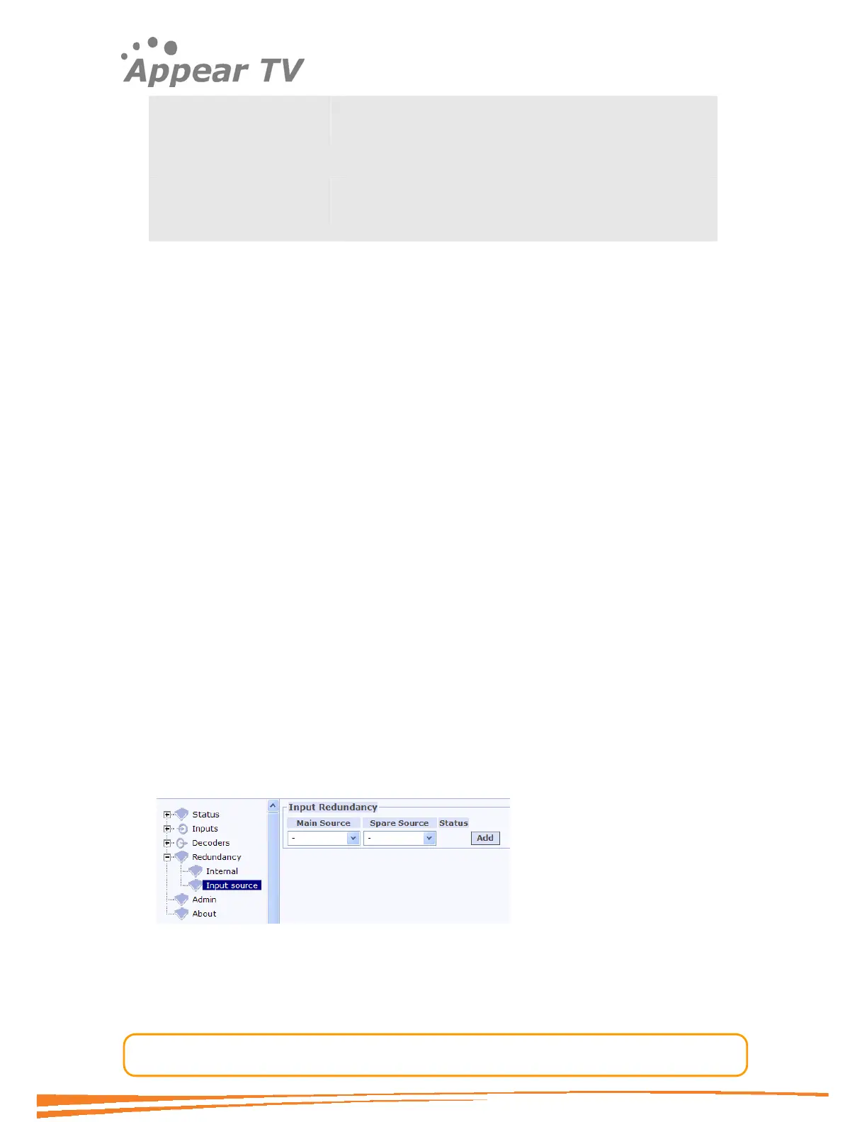
Configuring an input module as either main or backup:
Once IP modules are inserted, and the main module configured, clicking the Input
tab under the Redundancy tab in the navigation pane will open the Input
Redundancy setup display
Figure 22 - Source redundancy setup
To configure input redundancy, select the modules to be used as main source and
spare source from the pull down menus. Then click Add to add the redundancy
configuration to the system.