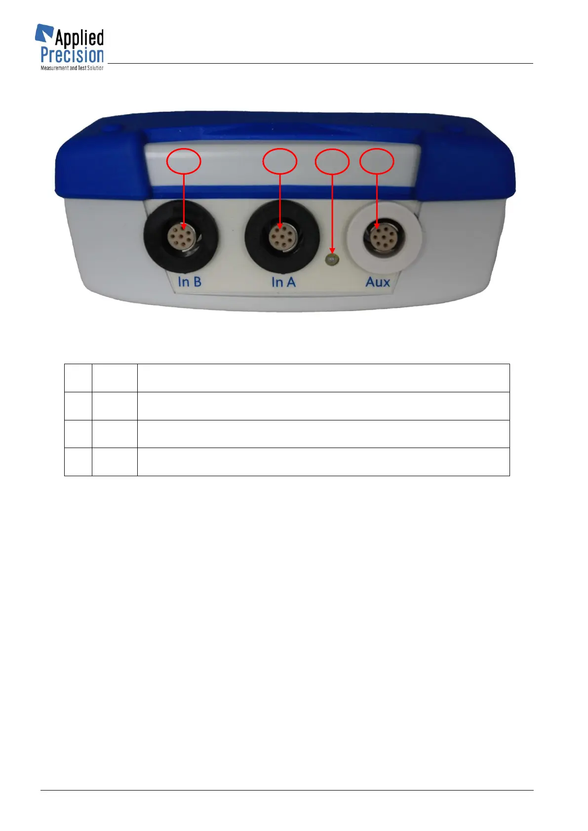
Accessories connectable into Auxiliary (AUX) Input / Output connector:
• Optical Sensor
• Impulse Input Base (for connection of Snap Switch or Impulse SO cable)
• Frequency Output with BNC adapter
Accessories connectable into Signal Input A or Signal Input B:
• Voltage Transducer VT 2x60 (max. voltage 600 V)
• Voltage Transducer VT 3x30 (max. voltage 500 V)
• Current Transducer CT 3x20 (max. current 20 A)
• Current Clamps CC 2x12 (max. current 120 A)
• Current Clamps CC 3x24 (max. current 240 A)
• Flexible Current Probe FCP (max. current 6000 A)
Remarks:
Signal Input A and Signal Input B are fully interchangeable and both can be used for connection of any
of above listed accessories. It is also possible to connect same type of accessories in both signal inputs.