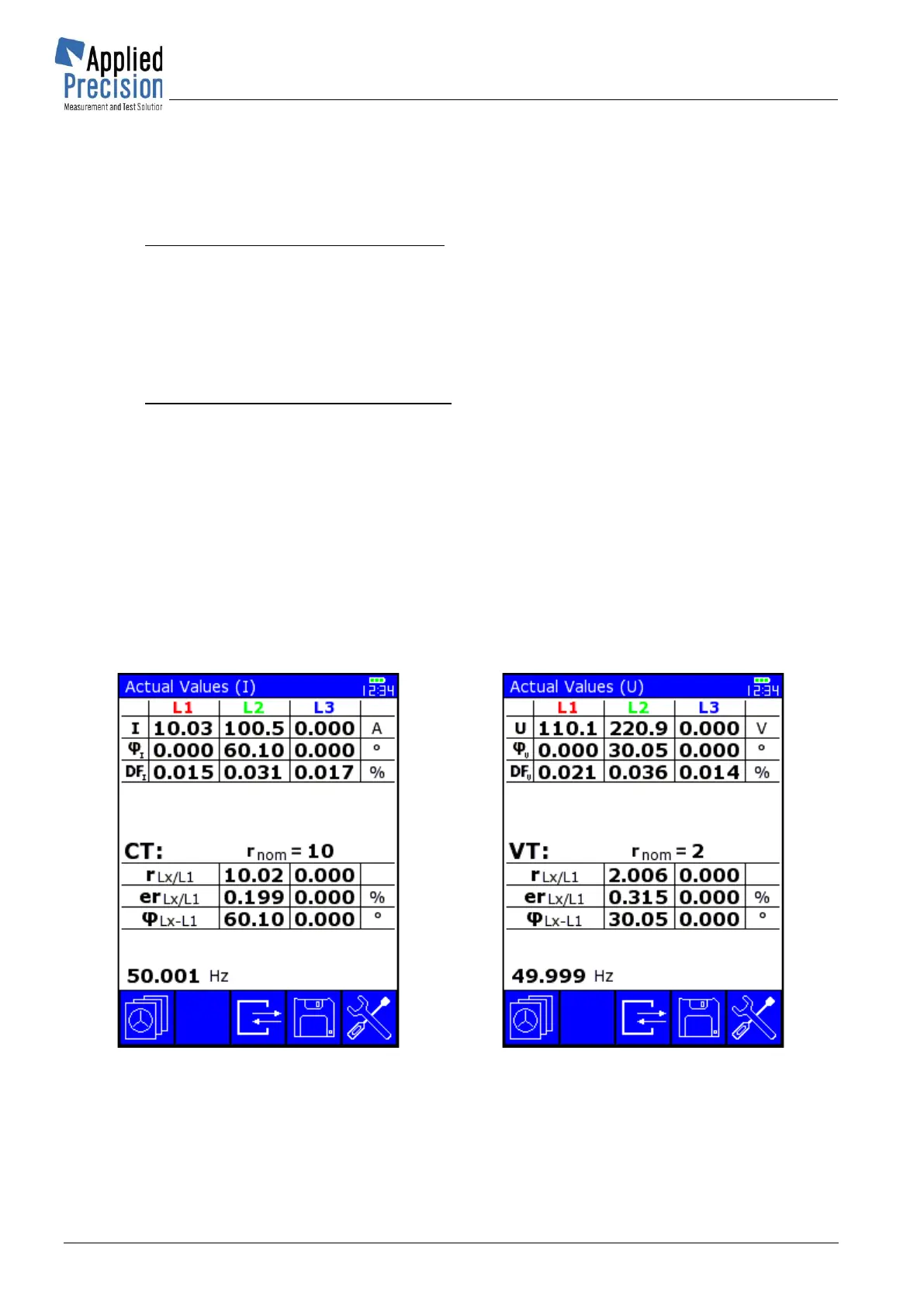
4.5.2 Actual Values
Actual Values screens show actual measured and calculated values of load point when other
combination than one current and one voltage measurement sensors are used.
Device shows measured and calculated values of Current (CT) and Voltage (VT) Transformers.
In case of connection of one measurement sensor device shows:
• Basic quantities (depends on used sensor)
• Transmission Ratio r
Lx/L1
• Transmission Error er
Lx/L1
• Phase Error φ
Lx/L1
Left values are comparison of values in phases L2 and L1 and right values in phases L3 and L1.
In case of connection of two measurement sensors device shows:
• Basic quantities (depends on used sensors)
• Transmission Ratio r
B/A
• Transmission Error er
B/A
• Phase Error φ
B/A
Showed values in each phase are comparison of values in Input A and Input B.
Transmission Error is calculated as comparison of measured Transmission Ratio (r
Lx/L1
or r
B/A
) and
nominal Transmission Ratio (r
nom
).
Content of Actual Values screens depends on connected measuring accessories.
Actual Values screens for WS 2320: