RANGE (Input A / Input B) ....... Settings of ranges for both measurement inputs (this part of settings
is stored in SD card, but only for particular accessory. If other
accessory is used, default values will be loaded. Accessory is
identified by its serial number)
Auto ............................. Automatic range selection: ON (enabled) or OFF (disabled). Device
chooses best suitable range depending on measured values if
automatic range selection is enabled.
Value ........................... Manually selected range (valid if parameter Auto is OFF)
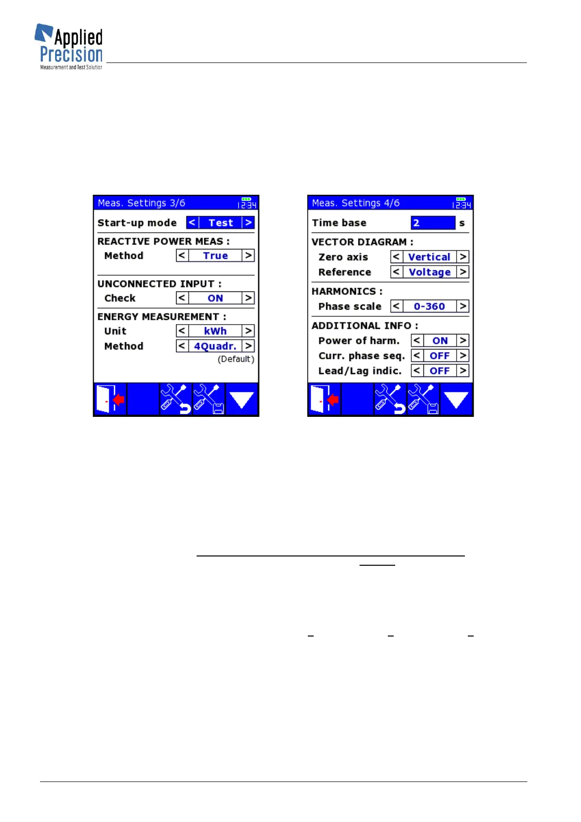
Start-up mode ........................ Defines initial measurement settings (Connection type, System,
Energy, Constant, Unit) activated right after device power up:
Meas. determines last settings used before switch-off,
Test defines parameters of last used meter from database.
REACTIVE POWER MEAS ..... Setting of reactive power measurement
Method ........................ Measurement method: True, Cross, Shift or Fund. f.
Remark: method Fund. f. is available only from firmware v. 5.69
Description of supported reactive power meas. methods:
True … classic calculation:
. The sign is determined by
reactive power calculated from Shift method. This method’s result is
considered by IEEE 1459-2010 as nonactive power. IEEE 1459-2010
defines only nonactive power and fundamental reactive power.
Cross … calculation from artificial connection:
Rem: The system must be balanced for achieving correct values! This
method is valid only in 3-phase connections with phase sequence L123. In
3-phase system with phase sequence L132 this method calculates results
with opposite sign.
Shift … calculation from U and I where current is shifted by ¼ of
period in time domain: . This approach is mentioned in
Annex A of IEEE 1459-2010.
Rem: Method does not consider higher harmonic components correctly!