7 Timers 63
CW6632B Bluetooth 3.0 Audio Player SOC Version 1.0.0
Copyright ©2015, www.appotech.com. All Rights Reserved.
100 = Timer0 counts at every 16 counting source events
101 = Timer0 counts at every 32 counting source events
110 = Timer0 counts at every 64 counting source events
111 = Timer0 counts at every 128 counting source events
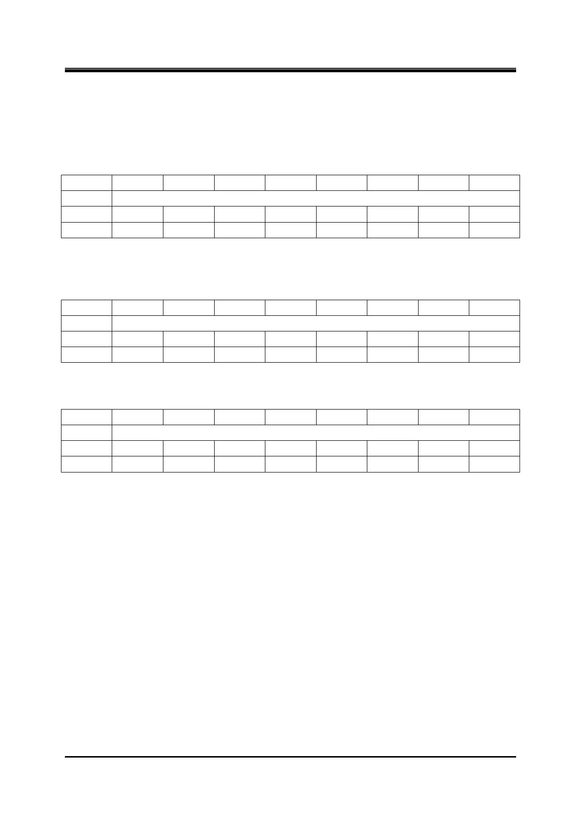
Register 7-2 TMR0CNT – Timer0 Counter
Note: Timer0 will increase in proper condition while it is enabled. It overflows when TMR0CNT = TMR0PR,
TMR0CNT will be clear to 0x00 when overflow occurs, and the interrupt flag will be set „1‟ by hardware.
Register 7-3 TMR0PR – Timer0 Period
Note: The overflow period of the timer is: T
inc-source
* T0PSR * (T0PR + 1).
Register 7-4 TMR0PWM – Timer0 PWM duty
Note: TMR0PWM is reserved in timer/counter mode. In PWM mode, it is used as duty cycle setting. In capture
mode, the value of TMR0CNT will be captured to TMR0PWM when selected event occurs.
7.2 Timer1
Timer1 is a 16-bit timer/counter with a 7-bit prescaler. It can be configured as timer, counter or PWM generator. X
7.2.1 Timer1 Features
16bits counter
7bits pre-scaler
Counter mode (clock source from system clock or TMR1)
Capture mode (event source from CAP1)
PWM mode (PWM signal output to PWM1)