7 Timers 65
CW6632B Bluetooth 3.0 Audio Player SOC Version 1.0.0
Copyright ©2015, www.appotech.com. All Rights Reserved.
T1CIE: Timer1 Capture mode Interrupt Enable Bit
0 = Disable
1 = Enable
T1PSR: Timer1 Prescaler
000 = Timer1 counts at every counting source event
001 = Timer1 counts at every 2 counting source events
010 = Timer1 counts at every 4 counting source events
011 = Timer1 counts at every 8 counting source events
100 = Timer1 counts at every 16 counting source events
101 = Timer1 counts at every 32 counting source events
110 = Timer1 counts at every 64 counting source events
111 = Timer1 counts at every 128 counting source events
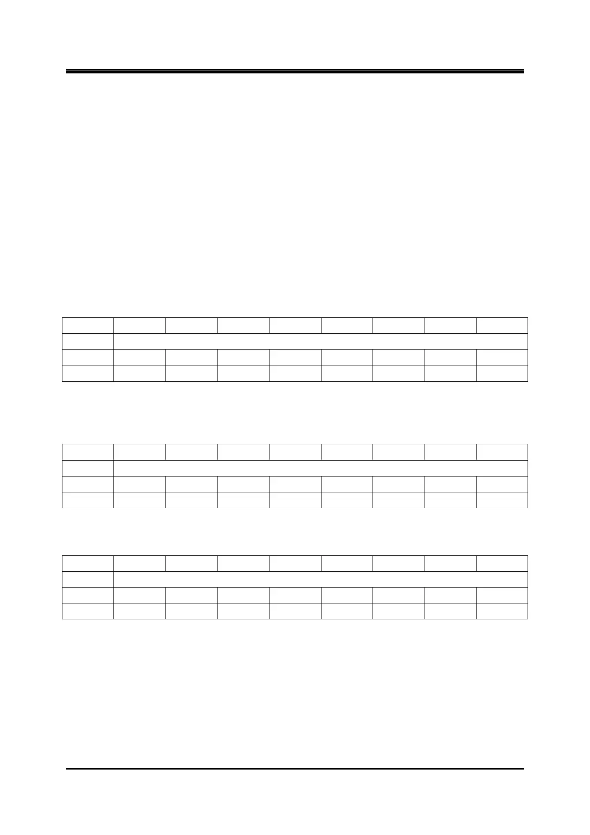
Register 7-7 TMR1CNTH/TMR1CNTL – Timer1 Counter
Note: Timer1 will increase in proper condition while it is enable, it overflows when TMR1CNT = TMR1PR,
TMR1CNT will be cleared to 0x0000 when overflow, and the interrupt flag will be set „1‟ by hardware.
Register 7-8 TMR1PRH/TMR1PRL – Timer1 Period
The overflow period of the timer is: Tinc-source * T1PSR * (T1PR + 1).
Register 7-9 TMR1PWMH/TMR1PWML – Timer1 PWM duty
Note: TMR1PWM is reserved in timer/counter mode. In PWM mode, it is used as duty cycle setting. In capture
mode, the value of TMR1CNT will be captured to TMR1PWM when selected event occurs.
7.3 Timer2
Timer2 is a 16-bit timer/counter with a 7-bit prescaler. It can be configured as timer, counter or PWM generator. X