7 Timers 67
CW6632B Bluetooth 3.0 Audio Player SOC Version 1.0.0
Copyright ©2015, www.appotech.com. All Rights Reserved.
0 = Not Pending
1 = Pending
T2TIE: Timer2 over Flow Interrupt Enable Bit
0 = Interrupt Disable
1 = Interrupt Enable
T2CIE: Timer2 Capture mode Interrupt Enable Bit
0 = Disable
1 = Enable
T2PSR: Timer2 Prescaler
000 = Timer2 counts at every counting source event
001 = Timer2 counts at every 2 counting source events
010 = Timer2 counts at every 4 counting source events
011 = Timer2 counts at every 8 counting source events
100 = Timer2 counts at every 16 counting source events
101 = Timer2 counts at every 32 counting source events
110 = Timer2 counts at every 64 counting source events
111 = Timer2 counts at every 128 counting source events
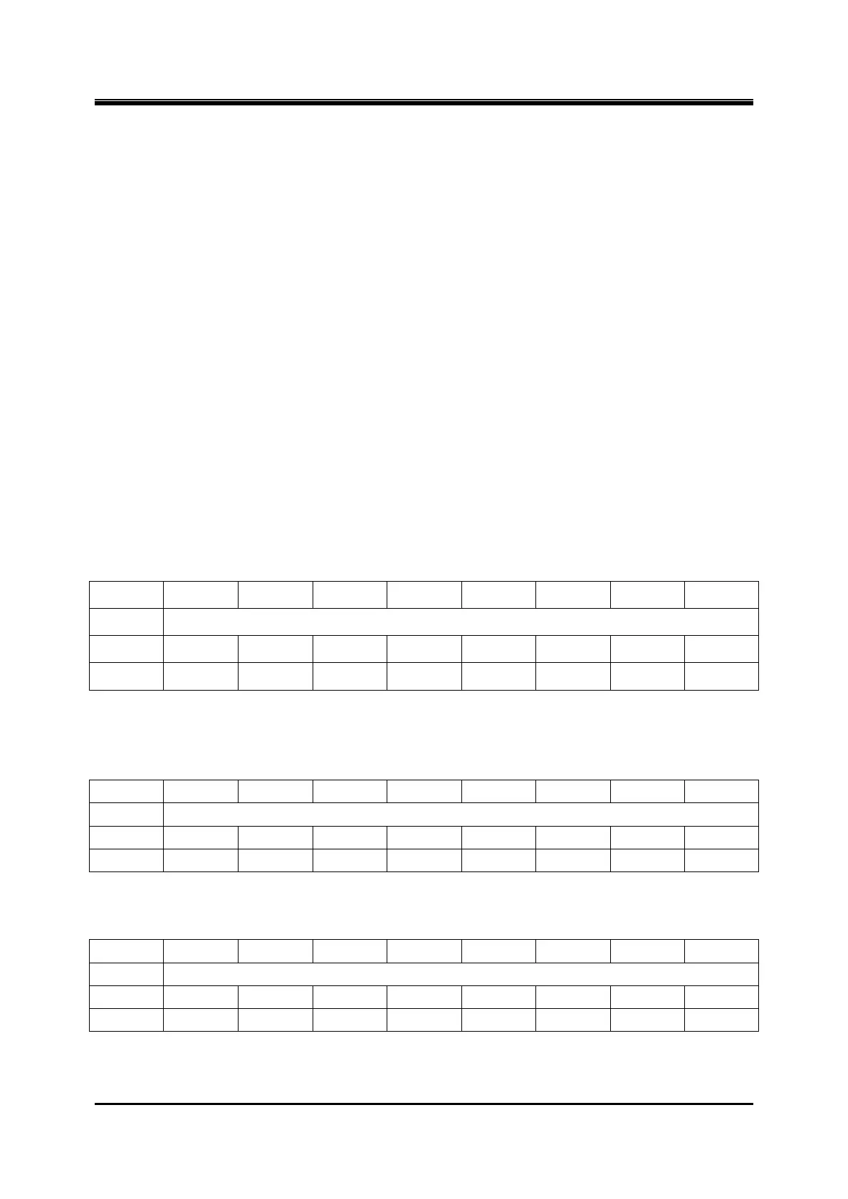
Register 7-12 TMR2CNTH/TMR2CNTL – Timer2 Counter
Note: Timer2 will increase in proper condition while it is enable, it overflows when TMR2CNT = TMR2PR,
TMR2CNT will be clear to 0x0000 when overflow, and the interrupt flag will be set „1‟ by hardware.
Register 7-13 TMR2PRH/TMR2PRL – Timer2 Period
The overflow period of the timer is: Tinc-source * T2PSR * (T2PR + 1).
Register 7-14 TMR2PWMH/TMR2PWML – Timer2 PWM duty
Note: TMR2PWM is reserved in timer/counter mode. In PWM mode, it is used as duty cycle setting. In capture
mode, the value of TMR2CNT will be captured to TMR2PWM when selected event occurs.