- 17 -
English
4.3 COMPONENTS REQUIRED FOR INSTALLATION
Components required for installation
1
2
3
9
11
4
8
10
7
5
6
12
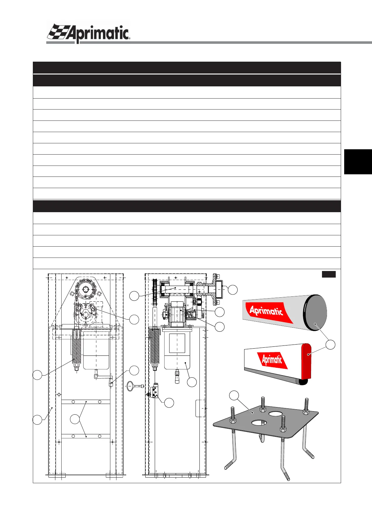
The following components are required when installing the barrier:
Pre-assembled barrier body - consisting of:
Asynchronous, single phase motor with external cooling fan ...........................................fig.1-ref.1
Irreversible, endless screw reducer ...................................................................................fig.1-ref.2
Lever system with roller bearings .......................................................................................fig.1-ref.3
Barrier support shaft ...........................................................................................................fig.1-ref.4
Electro-mechanical limit switch ..........................................................................................fig.1-ref.5
Removable crank for emergency manual operation ..........................................................fig.1-ref.6
Support plate for electronic control unit ..............................................................................fig.1-ref.7
Protection panel with key ...................................................................................................fig.1-ref.8
Safety micro-switch mounted on panel ..............................................................................fig.1-ref.9
This instruction manual is supplied with the barrier body.
In addition, the following items must be purchased separately - refer to the Aprimatic sales catalogue:
Balancing spring .................................................................................................................fig.1-ref.10
Barrier mounting flange ......................................................................................................fig.1-ref.11
Barrier cut to the required length ........................................................................................fig.1-ref.12
Alignment plate, complete with tie bolts for fixing to the ground (optional) ........................fig.1-ref.13
Electronic control unit (complete with instruction manual)
fig.1
13