2.6 Water supply for water flushed seals
If seal flushing is required, connect the flushing liquid to the pump.
Pumps fitted with a liquid-flushed mechanical shaft seal have 2 hose
connectors for flushing liquids in the seal housing. The hose
connectors are M5 and fit a Ø6.0 mm hose. See “Accessories
Manual 8.1, Shaft seal” for operating specifications.
Do not use these connections for flushing with steam or steam
condensate. If steam or condensate flush is required, a special
aseptic piping must be used.
Before starting the pump, remove any dirt, debris or foreign objects
which may have collected in the rotor chamber.
The rotors should be removed from the pump during the cleaning of
the system before start-up. Flushing plugs can be used, see spare
part manual.
Use the sectional drawing for reference.
3.1 Checking the pump for foreign objects:
1. Disconnect the power supply.
2. Undo and remove the front cover bolts (2,3,4) in the
front cover (1)
3. Use the two large bolts with full length thread (2) as jacking
screws in the threaded holes in the front cover (1). The front
cover is removed by turning each bolt one turn at a time - this
ensures that the front cover is removed in an even manner.
Remove the front cover (1).
4. Rotate the rotors (35) by manually turning the coupling between
pump and motor, to ensure that there are no foreign objects
behind the rotors.
5. Any foreign objects in the pump, must be removed. Clean with
air or water, removing the rotors if necessary. See 4.2
6. Re-fit front cover gasket (5) in rotor case (9).
7. Re-fit the front cover (1) by positioning it on the dowels (7) in the
rotor case (9), if fitted, tapping it gently in place with a plastic
mallet, and fastening the front cover bolts (2, 3, 4) to the
appropriate torque. See section 6.1.
8. Rotate the rotors (35) by manually turning the coupling between
pump and geared motor carefully to ensure freedom of
movement of the rotors inside the pump.
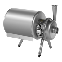
3.2 Check the following before finishing the installation:
- that the oil level of the pump is visible in the oil level window (25)
as shown in fig. 2.
NOTE:
The oil level window should be mounted on the side that gives the
highest oil level. The oil level window is above centreline. See fig. 19.
2 Installation of the pump
3. Before start-up and starting the pump
Fig. 2
Pump type
DW1 DW2 DW3 DW4 DW5 DW6 DW7
Lubricant quantities
in Litre (ca.)
0.8 1.3 1.4 3 7 25 40
Fig. 19
Oliepåfyldningsstuds /
Oil filler plug
Olieskueglas /
Oil level window
Oliedrænprop /
Oil drain plug