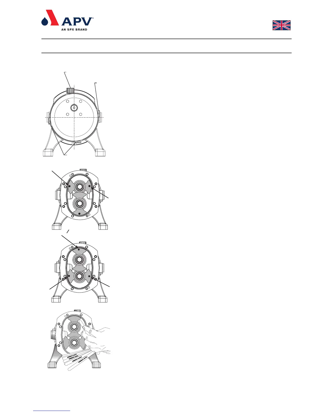
If the position of the feet and hence in- and outlet is changed, it
is necessary to change the position of the oil filler plug, the oil
level window etc. as shown in fig. 19.
NOTE:
Mount the plug (14) flush with the surface. Use Loctite 242.
4.9 Adjustment of the rotors axial position
To be able to operate the pump effectively and safely, it is necessary
to carry out the adjustment of the rotors axial position after having
dismantled and re-assembled the pump to ensure the correct axial
position of the two rotors. Use the sectional drawing for reference
(page 2).
The measured clearance should be as close to the clearances
described in section 6.8 as possible.
1. Measure the difference in depth between rotors (35) and rotor
case (9) by means of a depth micrometer. The points at which
you should measure the depths are shown in fig. 12 and 13.
Then the rotors are turned 180° and measured again. So that
twelve measurements are made in total.
2. Measure the rear clearance by means of feeler gauges. See fig.
14. Never go below the min. clearance stated in section 6.8. The
rear clearance should be measured at the same points as stated
in section 4.9 item 1.
3. Measure the radial clearance between rotor (35) and rotor casing
(9) by means of feeler gauges. The clearance should be
measured at the same rotor positions as stated in section 4.9
item 1.
4. If the clearances are not within the limits stated in section 6.8 or
if the distances measured able to be made closer to the mean
values stated in section 6.8, the rotors (35) are removed as
stated in section 4.2.
5. Remove the O-rings (36) situated on the shafts (38,39).
6. Remove the shims (37) of the shaft (38,39), measure the total
thickness of the shims with a micrometer, and add or subtract the
required amount of clearance to the shim thickness (e.g. if front
clearance is 0.1 mm too large, 0.1 mm must be added to the
total thickness of shims).
7. Refit shims (37) to the shafts (38,39). The thinner shims must be
inserted first.
8. Refit O-rings (36) on the shafts.
9. Refit rotors (35) as described in section 4.2.1.
10. Measure front and rear clearance again. If the clearances are
still outside the limits, or if they can come closer to the mean
values stated in section 6.8, repeat shimming procedure until the
measured clearances are correct.
11. When the front and rear clearances are correct, check that the
rotors (35) turn freely.
4. Dismantling and re-assembling the pump
Fig. 13
Fig. 14
Fig. 12
Oliedrænprop /
Fig. 19
Oliepåfyldningsstuds /
Oil filler plug
Olieskueglas /
Oil level window