There are a few basic operations to carry out during maintenance of
the pump. These are described in the following sections.
The sectional drawing shows the position of the various components
mentioned in this procedure.
4.1 Remove front cover (1):
To remove and re-fit the front cover (1) it is necessary to follow the
procedure as described below. Use the sectional drawing for
reference (page 2).
1. Disconnect the power supply to the motor.
2. Shut off the flushing supply, if fitted.
3. Close the isolating valves on the inlet and discharge side of the
pump.
4. Undo the front cover bolts (2,3,4). If the pump is used for hot
and/or aggressive liquids, special precautions must be taken. In
such cases, observe the local regulations for personal protection
when working with these products.
5. Use the two large bolts with full length thread (2) as jacking
screws in the threaded holes in the front cover (1). The front
cover is removed by turning each bolt one turn at a time - this
ensures that the front cover is removed the rotor case (9) in an
even manner. Remove the front cover (1).
4.1.1 Re-fit of the front cover:
1. Re-fit front cover gasket (5) in rotor case (9).
2. Re-fit the front cover (1) by positioning it on the dowels, if any,
(7) located in the rotor case (9), tapping it gently in place with a
plastic mallet, and fastening the front cover bolts (2, 3, 4) to the
appropriate torque. See section 6.1.
3. Rotate the rotors (35) by manually turning the coupling between
pump and geared motor carefully to ensure freedom of
movement of the rotors inside the pump.
4.2 Remove the rotors (35)
To remove and re-fit the rotors it is necessary to dismantle the pump
as described below. Use the sectional drawing for reference (page 2).
1. Remove the front cover (1) as described in section 4.1.
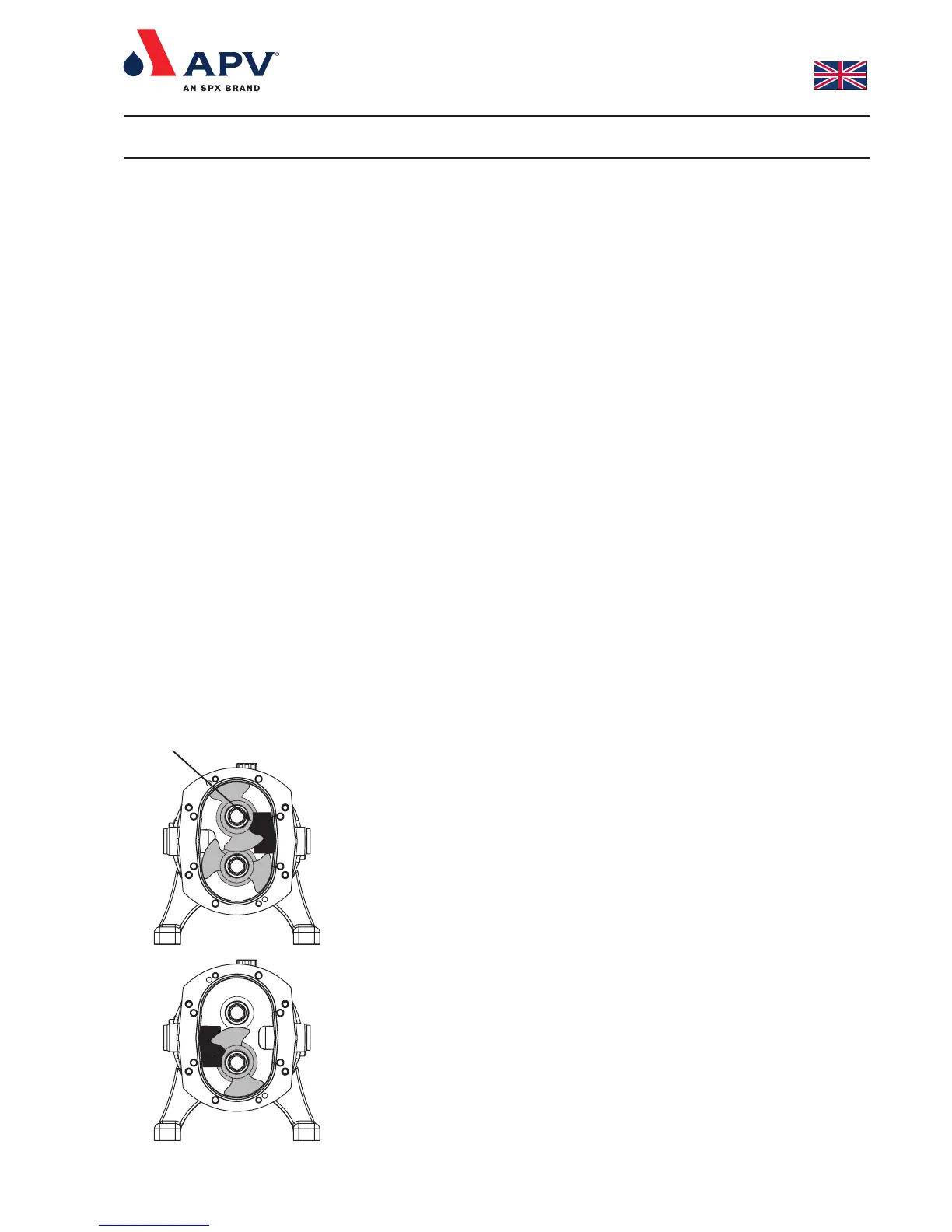
2. Position the rotors (35) and insert the fitting tool as shown in fig. 3.
3. Undo and remove the top or right rotor screw (32).
4. Remove the rotor locking piece and pull the rotor (35) out from
the shaft (38). Ensure that the wings of the other rotor are not
overlapping the hub of the rotor being pulled out.
5. Notice the marking of the rotors as shown in fig. 5. The rotors
are marked with respectively ‘L’ for the main (long) and ‘S’ for the
aux. (short) shaft. Notice that the rotors are marked on the back
with the serial number.
6. Position the rotor locking piece as shown in fig. 4.
7. Undo and remove the bottom or left rotor screw (32).
8. Remove the rotor (35) as before by pulling it out from the shaft
(39) with your fingers / special extractor.
4. Dismantling and re-assembling the pump
Fig. 4
Fig. 3
Rotor locking piece