4.2.1 Re-fit the rotors (35)
Check the contact surfaces (B, D) of the shaft seal for debris and
scratches. Use the section drawing for shaft sealing as reference
(page 5).
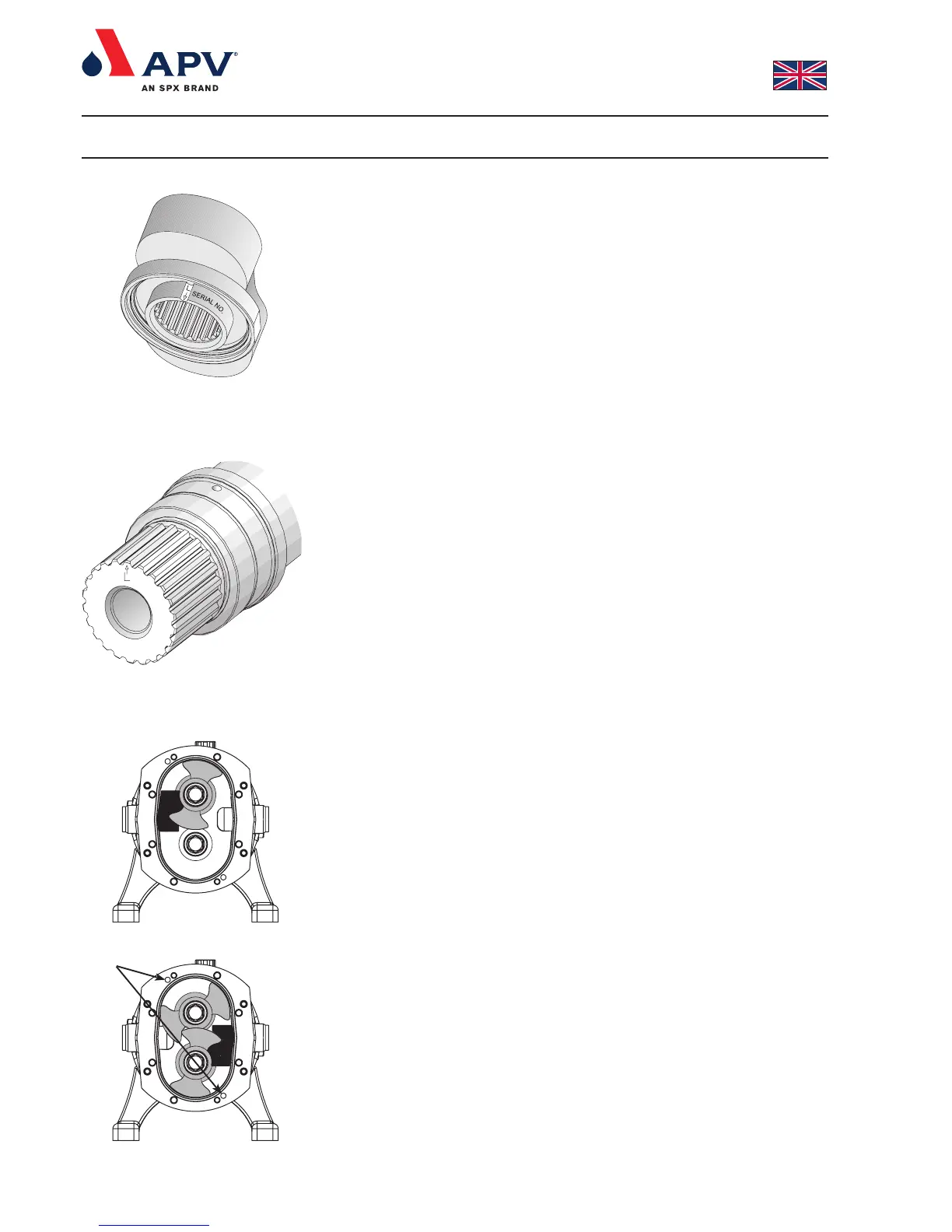
1. For re-fitting the rotors use the sectional drawing for reference
(page 2). Check on DW1-5 that the rotor marked with ‘L’ is
mounted on the main (long) shaft (38) and the rotor marked with
‘S’ is mounted on the aux. (short) shaft (39). See fig. 5.
Notice that the rotors are marked on the back with the serial
number.
On both DW6 and DW7 shafts and rotors are marked with ‘L’
and ‘S’ respectively - see fig. 5 and 6. Futhermore they are
marked with an arrow against the ‘L’ and ‘S’. At assembly the
arrow on the rotor and shaft must must be aligned. It is important
that shims are placed in the same position as before dismantling.
2. Re-fit top or right rotor (35) on the shaft (38).
3. Position the rotor (35) and the rotor locking piece as shown in
fig. 7 and tighten the screw (32) to the specified torque - see
section 6.1. Remove rotor locking piece.
4. Re-fit bottom or left rotor (35) on the shaft (39).
5. Position the rotor (35) and the rotor locking piece as shown in
fig. 8 and tighten the screw (32) to the specified torque - see
section 6.1. Remove rotor lock.
6. Rotate the rotors (35) by manually turning the coupling between
pump and geared motor carefully to ensure freedom of
movement of the rotors inside the pump.
7. Carry out shimming procedure as described in sections 4.9 and
4.9.1.
4.3 Remove the rotor case (9)
To remove and re-fit the rotor case (9) it is necessary to dismantle
the pump as described below. Use the sectional drawing for
reference (page 2).
1. Remove front cover (1) as described in section 4.1.
2. Remove rotors (35) as described in section 4.2.
3. Remove stationary seal rings (D), and seal O-rings (C) with your
fingers.
4. Disconnect the inlet and outlet ports of the pump from the
surrounding pipework.
5. Undo the bolts (6) that attach the rotor case (9) to the chassis
(13).
6. Remove the rotor case (9) by placing the bolts (6) into the two
tapped holes and turn each bolt one turn at a time.
4.3.1 Re-fit the rotor case (9)
1. Position the rotor case (9) on the dowels mounted in the chassis
(13) and use a plastic mallet to tap the rotor case home.
2. Re-fit and tighten the bolts (6) between the rotor case (9) and
the chassis (13) to the specified torque. See section 6.1.
3. Position the O-rings (C) on the shaft seal’s stationary seal ring
(D) and press the stator seal rings (the longer of the seal rings)
into the rotor case (9) without using tools. Keyways in the
stationary seal faces (D) must fit over drive dogs of the drive ring
(G) in the rotor case (9). Check correct mounting of the
stationary seal faces by feeling the spring force when mounting
them in the the rotor case (9).
4. Dismantling and re-assembling the pump
Fig. 7
Fig. 8
Tapped holes
Fig. 5
Fig. 6