4. Dismantling and re-assembling the pump
6. Undo the bottom or left gear nut (56).
7. Remove rotor lock and rotors (35) as described in section 4.2.
8. Straighten the locking tab on the washer (55) at the gears (54)
and remove the washers (55).
9. Pull the gears (54) off the shafts (38, 39) using an extractor. Note
by means of centre-punch marks which gear came off which
shaft.
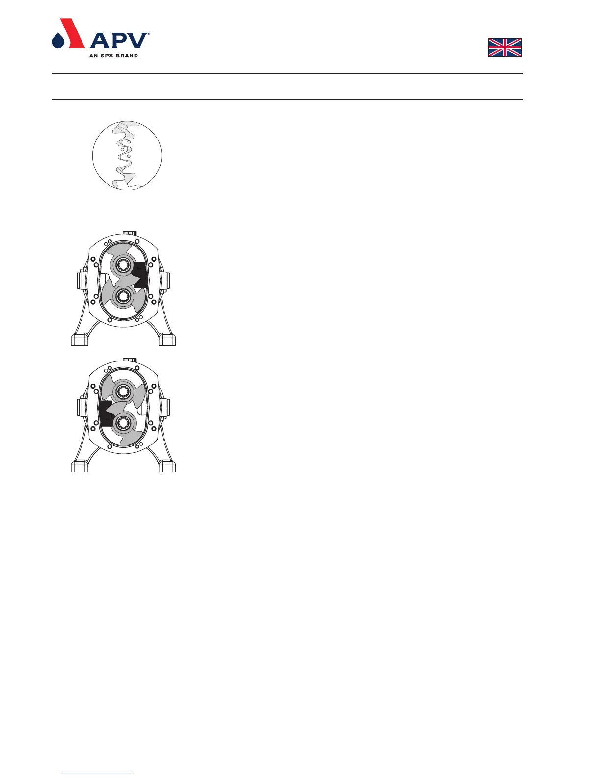
4.6.1 Re-fit the timing gears (54)
1. Refit the timing gears (54) onto the shafts (38, 39). Check that
the correct gear is fitted onto the correct shaft and correct
positioning of the gears as per fig. 10.
2. Position rotors (35) as described in section 4.2.1.
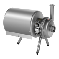
3. Position rotor locking piece as shown in fig. 3.
4. Position washer (55) and gear nut (56) onto the drive shaft (38)
and tighten the gear nut to the specified torque. See section 6.1.
5. Position rotor locking piece as shown in fig. 11.
6. Refit washer (55) and gear nut (56) onto the auxiliary shaft (39)
and tighten the gear nut to the specified torque - see section 6.1.
7. Bend the locking tabs on the tab washers (55).
4.7 Remove the oil seal plate (10)
To remove and re-fit the oil seal plate (10) it is necessary to
dismantle the pump as described below. Use the sectional drawing
for reference (page 2).
1. Remove the front cover (1) as described in section 4.1.
2. Remove the rotors (35) as described in section 4.2.
3. Remove the rotor case (9) as described in section 4.3.
4. Remove can (26) as described in section 4.4.
5. Remove the oil seal plate (10) by undoing and removing the nuts
(28) and pulling the front oil seal plate out.
4.7.1 Re-fit the oil seal plate (10)
1. Refit the oil seal plate (10) on to the shafts and tighten the nuts
(28) to the specified torque. See section 6.1.
Ensure that the O-rings (11) and lipseals (42) are placed in the
oil seal plate (10) before refitting.
4.8 Remove the foot (29, 30)
1. Undo and remove the screws (31). Use a hexagon socket wrench.
4.8.1 Re-fit the foot (29, 30)
1. Mount the screws (31). Use Loctite 242. Use a hexagon socket
screw wrench.
2. Align the assembly holes with the baseplate holes.
3. Tighten the screws (31) to the specified torque. See section 6.1.
Fig. 10
Fig. 3
Fig. 11