5. Maintenance
5. Move the feet (29, 30) to the required position as described in
sections 4.8 and 4.8.1.
6. Fill the gearbox with oil to the specified level according to fig. 2.
Check for leaks. See section 3.2 for required amount of oil and
positioning of oil level window.
5.4 Changing the bearings (45, 48)
To replace the bearings (45,45a,45b,48,48a,48b) it is necessary to
dismantle the pump as described below. Use the sectional drawing
for reference (page 2).
1. Remove the timing gears (54) as described in section 4.6
2. Remove gear key (40), shims (53), spacer (52) and circlip (51).
3. Straighten the locking tab on the tabwasher (49).
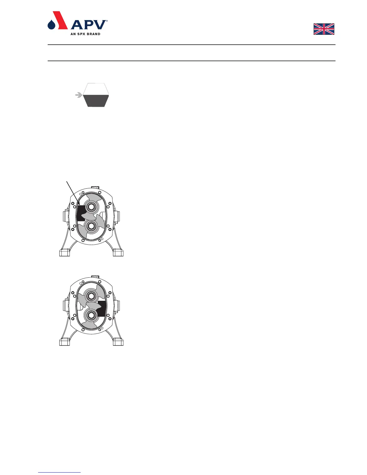
4. Position the rotor locking piece as shown in fig. 9, and undo the
drive shaft (38) bearing lock nut (50).
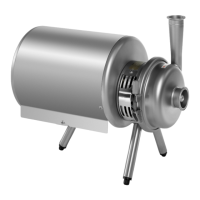
5. Reposition the rotor locking piece as shown in fig. 8.
6. Undo the auxiliary shaft (39) bearing lock nut (50).
7. Remove bearing nut (50) and tabwasher (49).
8. Remove the rotors (35) as described in section 4.2.
9. Remove the shims (if fitted) and shaft O-ring. Keep the shims
and O-ring together as a set for each shaft. Mark each set for
indentification to ensure later re-assembly on the correct shaft.
10. Remove rotor case (9) and the oil seal plate as described in
sections 4.3 and 4.7.
11. Remove shafts (38, 39) from the chassis (13) by applying force
to the rear of the shafts. During this process, the bearings should
be pushed free. Remove the shaft and bearings.
12. Remove outer bearing races (45b,48b) from the chassis and
inner bearing races (45a,48a) from the shafts (38,39). If the
shafts are damaged they should be replaced.
13. Clean the bearing seats of the chassis (13) and the shafts (38,39).
14. Fit new outer bearing races (45b,48b) and spacing washer (47)
in the chassis(13).
15. Fit the front inner bearing race (45a) on the shafts (38,39) by
heating the bearings.
16. Place both shafts (38,39) in the bore hole of the chassis.
17. Fit rear inner bearing race (48a), washer (49) and bearing lock
nut (50) on to the shafts (38,39).
18. Position the shims (44) and fit the oil seal plate (10), but without
lipseals (42).
19. Fit the rotor case (9) as described in section 4.3.1.
20. Fit the rotors (35) onto the shafts (38,39) (without- the shaft seal)
as described in section 4.2.1.
Fig. 2
Fig. 9
Fig. 8
Rotor locking piece