4.4 Remove can (26)
To remove and re-fit the can (26) it is necessary to dismantle the
pump as described below. Use the sectional drawing for reference
(page 2).
1. Disconnect the power supply.
2. Disconnect the pump from the geared motor. If possible, remove
the pump from the pipework and put it on a work bench.
3. Drain the oil from the pump by undoing the oil drain plug (27)
situated in the bottom of the can (26).
4. Remove drive key (43).
5. Remove the clamp ring (18).
6. Remove the can (26).
4.4.1 Re-fit can (26)
1. Check correct mounting of the O-ring (17).
2. Refit the can (26) over the shaft (38). Tighten the clamp ring (18)
to the specified torque. See section 6.1.
3.
Refit the oil level window (25), see fig. 19.
4. Fill the gearbox with the recommended oil to the specified level
according to fig.2. Check for leaks. See section 3.2 for required
oil amount.
4.5 Remove lipseal holder (20)
1. Remove can support (26) as described in section 4.4.
2. Remove screws (24)
4.5.1 Re-fit lipseal holder (20)
1. Check correct mounting of O-ring (21) and lipseal (22).
2. Mount screws (24) loosely.
3. Mount the can (26) as described in section 4.4.1.
4. Tighten the screws (24) for the lipseal holder (20) to the specified
torque - see section 6.1.
4.6 Remove the timing gears (54)
To remove and re-fit the timing gears (54) it is necessary to dismantle
the pump as described below. Use the sectional drawing for
reference (page 2).
1.
Remove can (26) as described in section 4.4.
2. Remove front cover (1) as described in section 4.1.
3. Position the rotors (35) and insert the rotor locking piece as
shown in fig. 9.
4. Straighten the locking tab on the washer of the gear nut (55) at
the gears (54) and undo the upper or right gear nut (56).
5. Re-position the rotor lock as shown in fig. 8.
4. Dismantling and re-assembling the pump
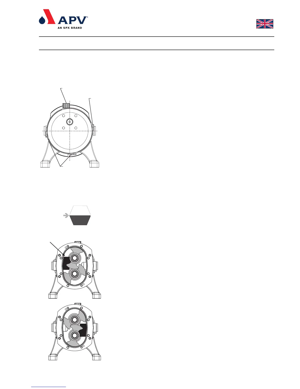
Fig. 2
Fig. 9
Rotor locking piece
Fig. 19
Oliepåfyldningsstuds /
Oil filler plug
Olieskueglas /
Oil level window
Oliedrænprop /
Oil drain plug
Fig. 8