4.9.1 Adjustment of the rotors angular position
To run the pump effectively and safely, it may be necessary to carry
out the adjustment of the rotors angular position after dismantling and
re-assembling it, to ensure the correct angular position of the two
rotors. Use the sectional drawing for reference (page 2).
NOTE:
Re-timing applies to lobe rotors only.
Re-timing is carried out as described below:
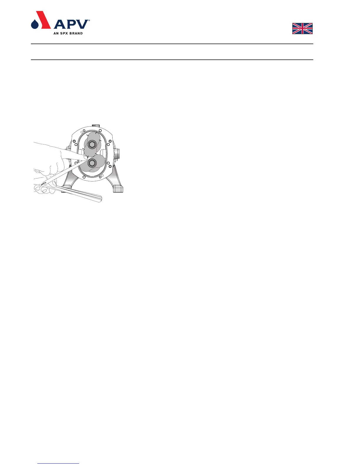
1. Measure the interlobe clearances with feeler gauges at the 6
positions as shown in fig. 15. If these clearances are outside the
tolerances stated in section 6.8. (column “Interlobe”), it is
necessary to re-time the rotors.
2. Remove can (26) as described in section 4.4.
3. Choose one of the shafts to work on. Straighten the locking tab
on the washer (55) and loosen the gear nut (56). (use e.g. a
wedge shaped object of soft material e.g. wood, plastic or nylon
wedged between the two wheels.) Ease the gear (54) max. 1
mm back along the shaft (it is important not to move the gear
more than the 1 mm as it can cause damage to the rotors
themselves).
4.
Re-check the clearances and see if the rotors have shifted in the
correct direction according to section 6.8. If the rotors have
shifted in the correct direction as wanted go to section 4.9.1 item
6.
5.
If the rotors have not shifted in the correct direction, retighten
the gear nut (56) to the specified torque as described in section
6.1 and bend the tab washer down again (55).
Return to section 4.9.1 item 3, but work on the other shaft.
6. Ease the second gear back along the shaft until the clearance
between the rotors are as described in section 6.8.
7. The new distance between the spacer (52) and the moved gear
(54) is measured with feeler gauges. Shims (53) with the total
thickness corresponding to the distance measured are selected.
8.
Remove the gear (54) and gear key (40) as described in section
4.6 from the shaft and fit the selected shims (53) on the shaft.
9. Re-fit gear key (40) and gear (54) as described in section 4.6.1.
Re-fit tab washer (55) and gear nut (56) and tighten it to the
specified torque as described in section 6.1.
10. Measure the interlobe clearances. If they are still not within the
tolerances stated in section 6.8 repeat the procedure starting
from section 4.9.1 item 3.
11.
Check that the rotors turn freely.
12. Refit the can (26) as described in section 4.4.1
4. Dismantling and re-assembling the pump
Fig. 15