5. Maintenance
5.2 Replacement of single mechanical shaft seals
To change shaft seal it is necessary to disassemble the pump as
de-scribed in the following. Use the sectional drawing for reference
(page 2 and 5).
1. Remove the front cover (1) as described in Section 4.1.
2. Remove the rotors (35) as described in Section 4.2.
3. Remove the stationary seal face (D) and the O-ring (C) with the
fingers
4. Check the new shaft seals contact surface for dirt and scratches.
5. Mount the new stationary seal face (D) and O-ring (C) in the
rotor casing (9) without using tools. The stationary seal face (D)
is the longer of the two shaft seal rings. The keyway in the
stationary seal face (D) must fit over the groove in the stationary
drive ring (G). Check that it is correctly fitted by feeling the
spring force (H) when it is pushed in over the shaft (38,39).
6. Remove the rotary seal face (B) and O-ring (C) from the rotor
(35).
7. Insert a new rotary seal face (B) and O-ring (C) in the rotor (35).
8. Mount the rotors (35) as described in Section 4.2.1.
9. Mount the front cover (1) as described in Section 4.1.1.
10. Check that the rotors turn freely.
NOTE:
All types of shaft seal (single lip seal, triple lip seal, single mechanical
seal, single mechanical seal with water flush, dual mechanical seal
and packed gland packing ) can all be mounted on the same pump.
This requires only the correct shaft seal kit. These kits are described
in the additional manual for shaft seals, “Accessories Manual 8.1,
Shaft seal”.
5.3 Changing port orientation
It is possible to change the suction and discharge port orientation
from horizontal to vertical and vice versa without making any
modifications to the pump.
To change the port orientation it is necessary to dismantle the pump
as described below. Use the sectional drawing for reference (page 2).
1. Disconnect the power supply to the motor.
2. Disconnect the pump from the motor. If possible, remove the
pump from the pipework and place it on a work bench.
3. Undo the oil drain plug (27) in the bottom of the can (26) to drain
the oil from the pump.
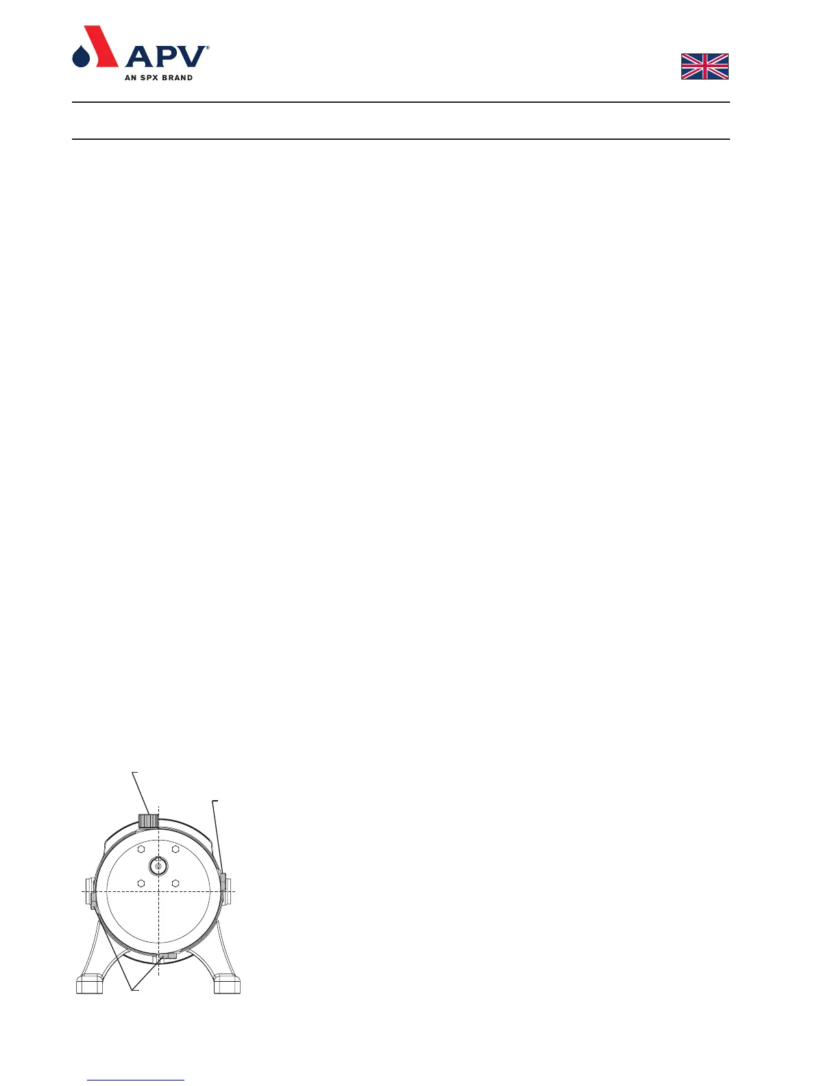
4. Exchange the plugs on the can (26). Orange oil filler plug (23) in
top position. The oil level window should be mounted on the side
that gives the highest oil level - oil level window (25) above the
centreline. Oil drain plugs (27) at the bottom and the side below
the centreline, see fig. 19.
Fig. 19
Oliepåfyldningsstuds /
Oil filler plug
Olieskueglas /
Oil level window
Oliedrænprop /
Oil drain plug