8
UK
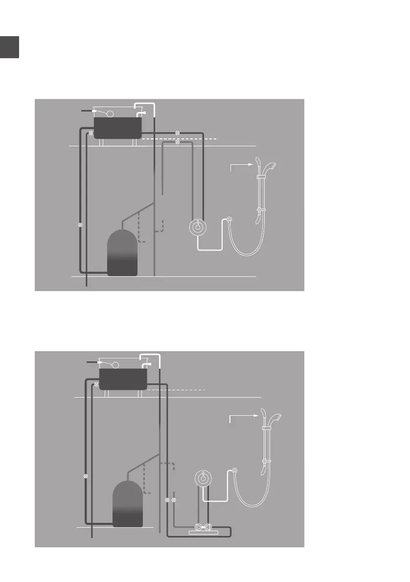
TYPICAL GRAVITY SYSTEM INSTALLATION
(suitable for use with Midas 110/220 shower valves)
Head to be 1m minimum
Refer to page 6 (siting)
TYPICAL GRAVITY BOOSTED SYSTEM INSTALLATION
(suitable for use with all Midas valves)
Refer to special notes on page 6*
Underside of cistern
Vent and draw-o
pipe to hot water
Cold feed
to cylinder
Supply
Typical gravity system installation
Typical pumped system installation
Typical combination boiler installation
Typical UHW system installation
Typical thermal storage unit system installation
Hot water
Connect
“A” or “B”
B
A
Highest point
must be below
underside of
cistern
Underside of cistern
Vent and draw-o
pipe to hot water
Cold feed
to cylinder
Pressure
reducing valve
if required
Supply
Supply
Supply
Supply
Hot water
cylinder
Hot water
cylinder
Central
heating
boiler
Connect
“A” or “B”
B
A
Highest point
must be below
underside of
cistern
Underside of cistern
Vent and draw-o
pipe to hot water
Cold feed
to cylinder
Supply
Typical gravity system installation
Typical pumped system installation
Typical combination boiler installation
Typical UHW system installation
Typical thermal storage unit system installation
Hot water
cylinder
Connect
“A” or “B”
B
A
Highest point
must be below
underside of
cistern
Underside of cistern
Vent and draw-o
pipe to hot water
Cold feed
to cylinder
Pressure
reducing valve
if required
Supply
Supply
Supply
Supply
Hot water
cylinder
Hot water
cylinder
Central
heating
boiler
Connect
“A” or “B”
B
A
Highest point
must be below
underside of
cistern