ST/BRIDGE/DM
MODE
XLR/RCA
INPUT
25dB/31dB
GAIN
L
R
PRE
IN
PRE
OUT
R
4–16 OHMS. CLASS 2 WIRING
SPEAKER 1 SPEAKER 2
L
4–16 OHMS. CLASS 2 WIRING
SPEAKER 2 SPEAKER 1
PRE IN R PRE IN L
110-120V/220-240V
~ 50-60 Hz
350W MAX
POWER INLET
SUPPLY
VOLTAGE
SWITCH POSITIONS
115 = 110 - 120V~
230 = 220 - 240V~
TRIGGER IN
TRIGGER OUT
PHONO
GROUND
ONLY
PHONO
(MM)
CD TUNER SAT BD PVR AV
RECORD
OUT
PRE
OUT
AUX R AUX L PRE OUT R PRE OUT L
TRIGGER OUT
6V 1A12V 1.5A
ACCESSORY
POWER
110-120V/220-240V
~ 50-60 Hz
350W MAX
POWER INLET
SUPPLY
VOLTAGE
SWITCH POSITIONS
115 = 110 - 120V~
230 = 220 - 240V~
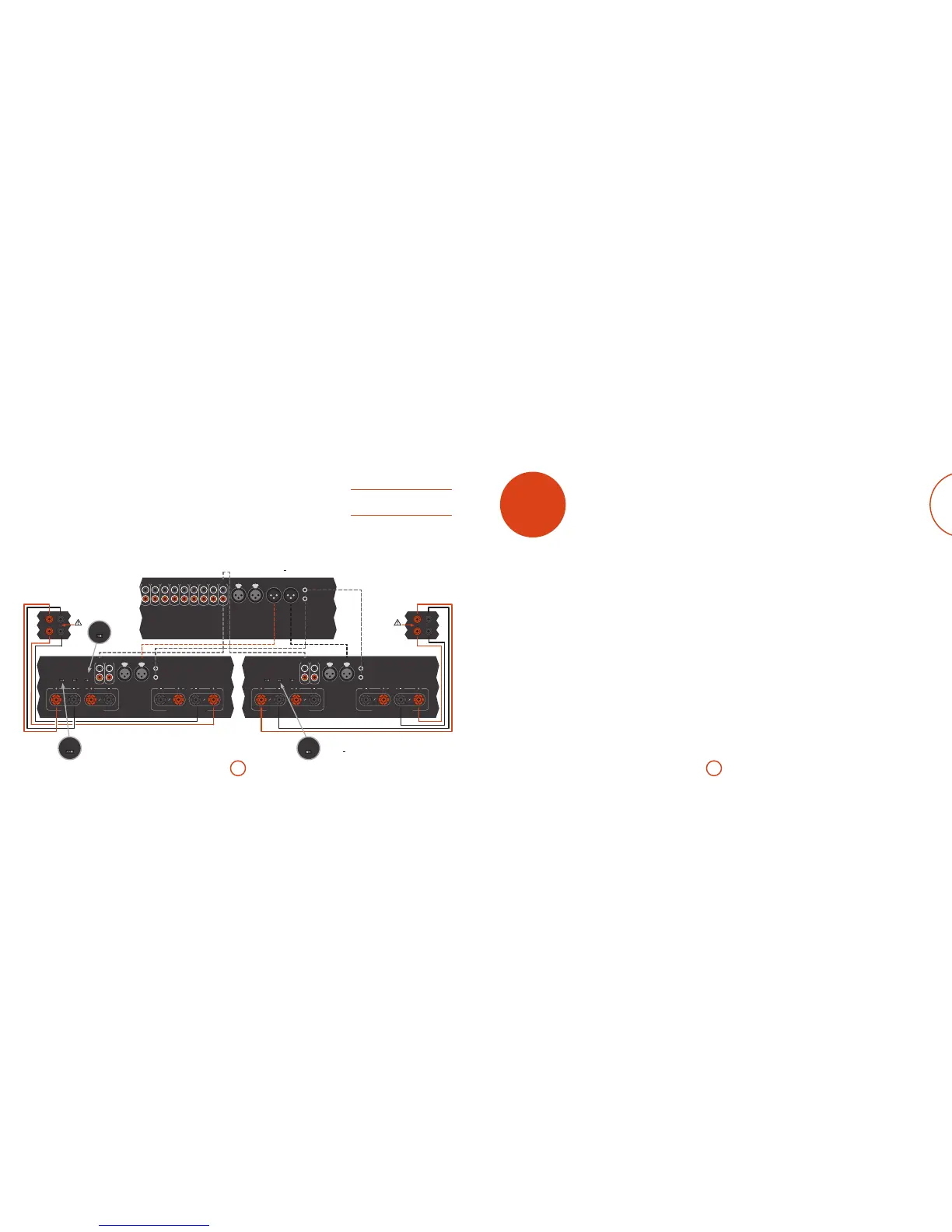
Dual mono - P49 only
Dual mono requires the use of a power amplier for
each channel.
We recommend that you use the SPEAKER 1 L set
of terminals on your P49 power amps for the low
frequencies and the SPEAKER 2 R set of terminals for the
high frequencies.
On one of the P49’s, connect the red positive speaker
terminal labelled SPEAKER 1 L+ to the positive LF terminal
of your right speaker. Similarly, connect the black
negative speaker terminal labelled SPEAKER 1 L to the
negative LF terminal of your right speaker. Repeat this
process for the le speaker, using the terminals labelled
SPEAKER 1 L+ and L on the other P49 power amp.
On the rst P49, connect the red positive speaker
terminal labelled SPEAKER 1 R+ to the positive HF
terminal of your right speaker. Similarly, connect the
black negative speaker terminal labelled SPEAKER 1 R to
the negative HF terminal of your speaker. Repeat this
process for the le speaker, using the terminals labelled
SPEAKER 1 R+ and R on the second P49.
In this setup only one interconnect is required to each
power amplifer and it should be connected to the
PRE IN L input. e interconnects can be either XLR
(recommended for longer cable runs) or phono (RCA).
Set the INPUT switch on the P49’s to the appropriate
setting for the cables used.
Note: PRE IN R has no function in this arrangement.
WARNING: the strip of metal on the speakers connecting
the low frequency (LF) terminals to the high frequency (HF)
terminals MUST BE REMOVED. Failure to do so will result
in damage to both ampliers, which will not normally be
covered under warranty.
To allow the power state of the P49 to be controlled by
the A49 please connect the TRIGGER OUT to the TRIGGER
IN using a mono 3.5mm jack lead – not supplied.
R
A C49 pre-amp and two P49 power amps in dual mono configuration.
ST/BRIDGE/DM
MODE
XLR/RCA
INPUT
25dB/31dB
GAIN
L
R
PRE
IN
PRE
OUT
R
4–16 OHMS. CLASS 2 WIRING
SPEAKER 1 SPEAKER 2
L
4–16 OHMS. CLASS 2 WIRING
SPEAKER 2 SPEAKER 1
PRE IN R PRE IN L
110-120V/220-240V
~ 50-60 Hz
350W MAX
POWER INLET
SUPPLY
VOLTAGE
SWITCH POSITIONS
115 = 110 - 120V~
230 = 220 - 240V~
TRIGGER IN
TRIGGER OUT
L
C49
P49 P49
Remove
metal strip
Remove
metal strip
Make sure MODE
switch is set to DM
on both amps
Make sure INPUT
switch matches wired
configuration (XLR or RCA)
on both amps
ST/BRIDGE/DM
MODE
ST/BRIDGE/DM
MODE
ST/BRIDGE/DM
MODE
XLR/RCA
INPUT
XLR/RCA
INPUT
25dB/31dB
GAIN
25dB/31dB
GAIN
NOTE: Units can be interconnected via XLR or RCA.
Both versions shown for illustration purposes only.
Make sure GAIN
switch is set to 31dB
on both amps
ST/BRIDGE/DM
MODE
ST/BRIDGE/DM
MODE
ST/BRIDGE/DM
MODE
XLR/RCA
INPUT
XLR/RCA
INPUT
25dB/31dB
GAIN
25dB/31dB
GAIN
ST/BRIDGE/DM
MODE
ST/BRIDGE/DM
MODE
ST/BRIDGE/DM
MODE
XLR/RCA
INPUT
XLR/RCA
INPUT
25dB/31dB
GAIN
25dB/31dB
GAIN
troubleshooting
Sound cuts-out unexpectedly
If the temperature of the internal heatsink rises above
a safe level, then a thermal cut-out inside the amplier
operates to protect the unit and the protection system
temporarily removes power to the speakers. e system
will reset itself as the heatsink cools down.
< With two pairs of low-impedance speakers
connected (6Ω or less), overloads are more likely.
Overloading the amplier may cause it to shut
down because of overheating.
< Note that, due to the high output voltage from
some CD players, it is possible to drive your
amplier at full power even though the volume is
not set at maximum.
If you are having trouble with your amplier, check the
following items.
No sound
Check the following:
< e amplier is switched on.
< e A49/C49 is not muted (i.e. MT (mute) is not
shown on the display panel; the power LED is
showing green, not orange or red).
< e selected source going in to the A49/C49 is
generating audio (e.g., if CD is selected, then the
CD is playing).
< e speaker outputs on the A49/P49/P349 are
active and the appropriate speaker LED is showing
green.
No remote control
Check the following:
< Check the remote control with fresh batteries.
< Ensure that the amplier and remote are both set to
the same control code - see page17.
< If the volume does not operate for a selected input,
check that processor mode has not been selected for
that input - see page12.