6
ATV2183
To access the indicator light connector for testing pur-
poses, use the following procedure.
1. Remove the seat and body (see Section 8).
2. Disconnect the four-wire connector from the main
wiring harness.
NOTE: For these tests, a 12-volt power supply
“jumper” should be used to supply power.
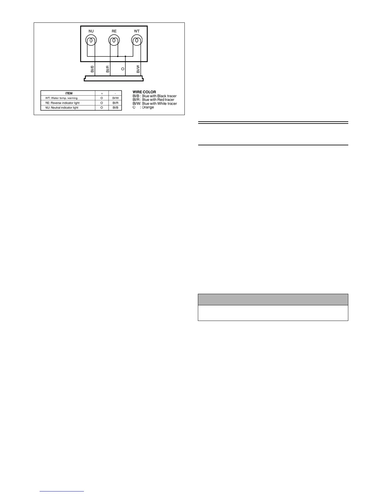
WATER TEMPERATURE INDICATOR
LIGHT
1. Connect the jumper positive wire to the power
source terminal on the indicator light connector.
2. Connect the jumper ground wire to the blue/white
(temperature) wire on the indicator light connector.
3. The water temperature indicator light should illumi-
nate.
NEUTRAL INDICATOR LIGHT
1. Connect the jumper positive wire to the power
source terminal on the indicator light connector.
2. Connect the jumper ground wire to the blue/black
(neutral) wire on the indicator light connector.
3. The neutral indicator light should illuminate.
REVERSE INDICATOR LIGHT
1. Connect the jumper positive wire to the power
source terminal on the indicator light connector.
2. Connect the jumper ground wire to the blue/red
(reverse) wire on the indicator light connector.
3. The reverse indicator light should illuminate.
NOTE: If a light fails to illuminate in any one of
the indicator light tests, the connector, wiring har-
ness, or a bulb must be replaced.
INDICATOR LIGHTS VOLTAGE
NOTE: The ignition switch must be in the ON
position, and the test must be performed on the
lower side of the connector.
1. Set the meter selector to the D.C. Voltage position.
2. Connect the red tester lead to the orange wire; then
connect the black tester lead to ground.
3. The meter must show battery voltage.
NOTE: This is the only voltage test for all indica-
tor lights.
After testing procedures are completed, use the following
procedure.
1. Connect the indicator light four-wire connector to
the main harness.
2. Install the body and seat (see Section 8).
Ignition Switch
The connector is the three-wire one in front of the
steering post. To access the connector, the body and
seat must be removed (see Section 8).
VOLTAGE
NOTE: Perform this test on the lower side of the
connector.
1. Set the meter selector to the D.C. Voltage position.
2. Connect the red meter lead to the red wire; then con-
nect the black meter lead to ground.
3. Meter must show battery voltage.
NOTE: If the meter shows no battery voltage,
troubleshoot the battery or the main wiring har-
ness.
RESISTANCE
NOTE: Perform this test on the upper side of the
connector.
1. Turn the ignition switch to the ON position.
2. Set the meter selector to the OHMS position.
3. Connect the red tester lead to the red wire; then con-
nect the black tester lead to the orange wire.
4. The meter must show less than 1 ohm.
5. Turn the ignition switch to the LIGHTS position.
6. Connect the red tester lead to the red wire; then con-
nect the black tester lead to the orange wire.
7. The meter must show less than 1 ohm.
8. Connect the red tester lead to the red wire; then con-
nect the black tester lead to the gray wire.
9. The meter must show less than 1 ohm.
! CAUTION
Always disconnect the battery when performing
resistance tests to avoid damaging the multimeter.