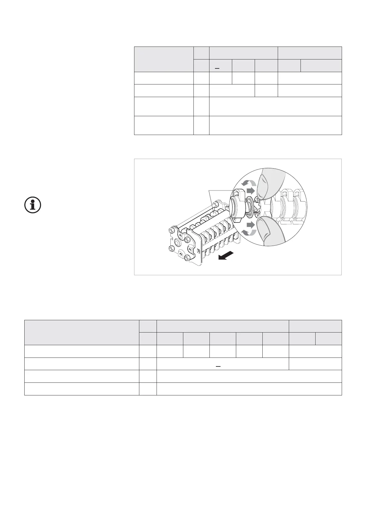
Other switching functions of the au-
xiliary switch can be set by adjusta-
ble cams (Fig. 2.2).
Important:
The auxiliary switches may
only be set by specialists
who dispose of experience
regarding the auxiliary switches in-
stalled. Auxiliary switches must not
be disassembled.
10
Auxiliary switch
Auxiliary switches are always actua-
ted directly by the switch shaft via an
intermediate linkage. Their position
always corresponds to that of the
main contacts.
The switching functions have been
set in the factory according to the
circuit diagram.
Rated supply voltage
DC AC
[V] 24 48 60 110 220 120 230
Switching capacity [A] 8 4 3 2 1 10
Time factor T=L/R [ms] < 20 –
Rated short-time current 100 A for a duration of 30 ms
Rated continuous current [A] 10
Fig. 2.2
Setting the cams of the auxiliary switch
Rated
supply voltage
DC AC
[V] <48 125 220 120 230
Switching capacity [A] 10 3,8 2 10
Time factor T=L/R [ms] 10 20 –
Rated short-time
current
250 A / 3 s
Rated continuous
current
[A] 15
Technical data of auxiliary switches for circuit-breaker (3 x 8-pole)
Cam
Viewing direction for
adjustment
Technical data of auxiliary switches on the withdrawable part for PIX high current panels
Auxiliary switch on the withdrawable part for PIX high current panels