Warning!
Observe the safety pro-
visions of chapter 1.5.
Warning!
Risk of injuries.
The energy storing de-
vice must not be char-
ged until assembly is finished.
5 Assembly
• Dimension drawings are made
available on request.
• Check technical data on name-
plate.
• Check supply voltage for the
control and operating devices in-
stalled.
The vacuum circuit-breakers HVX-F
and HVX-E are delivered in comple-
tely assembled and ready-to-operate
condition. They are supplied in posi-
tion "OFF" and with the energy sto-
ring device "released".
5.2 HVX-F – Mechanical assembly
Screws and attachments are not in-
cluded in the scope of supply.
Fastening the circuit-breaker
Warning!
The frame being used
must be suitable to
bear the weight of the
circuit-breaker (see Chapter 4).
Dimensions and arrangement of fas-
teners: see dimension drawing.
Important:
Comply with the specified
tightening torques (refer to
Annex).
Make sure not to distort the circuit-
breaker when screw-fastening it.
Earth terminal
• Design and dimensioning of the
circuit-breaker's earth terminal
acc. to IEC 62271-100.
• Select the cross section of and
the material used for the earth
conductor according to HD 637
S1 or the appropriate national
work instruction.
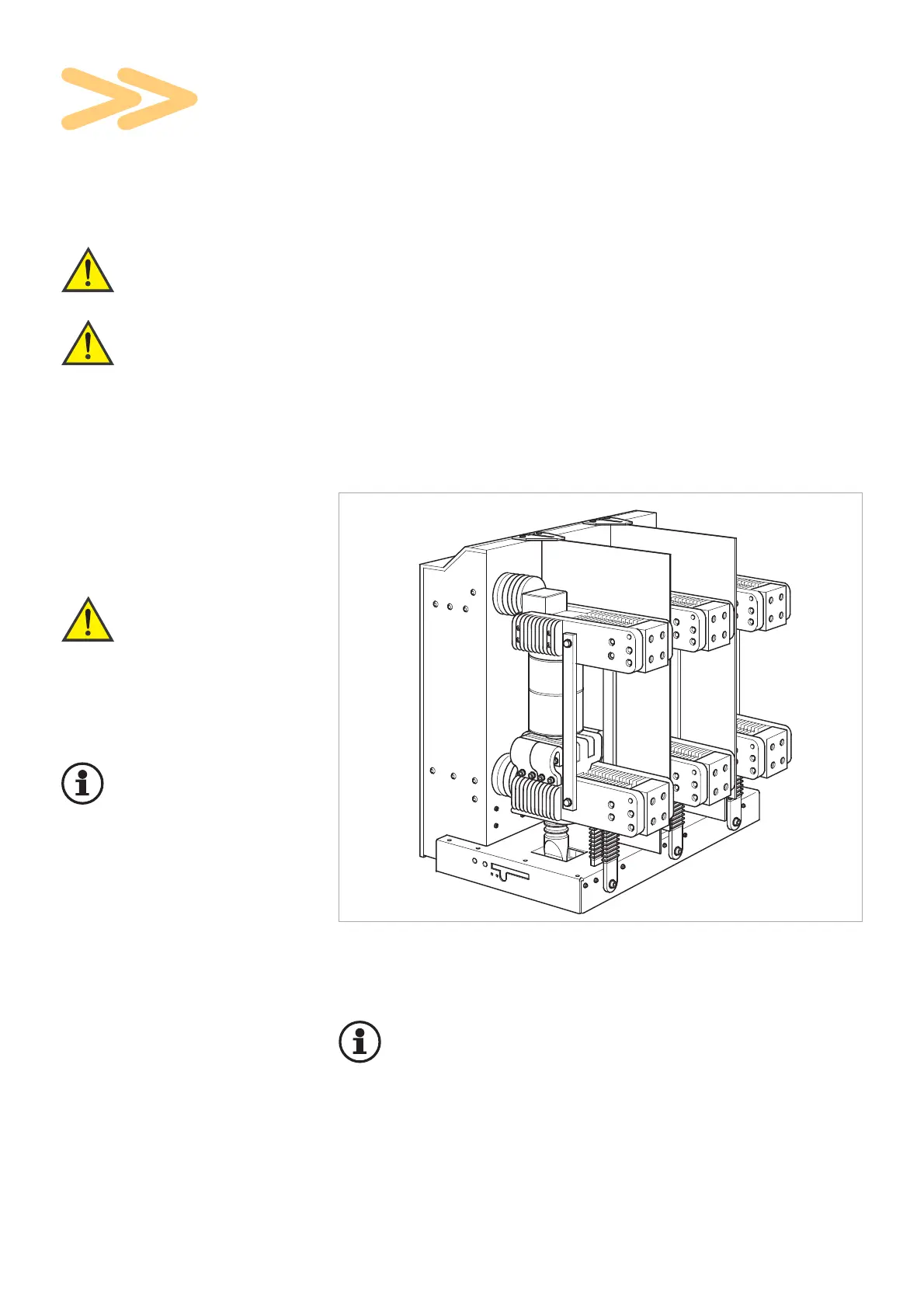
Fig. 5.1
HVX-F
Important:
Coat contact surfaces and
comply with the specified
tightening torques (refer to
Annex).
Connect earth line to the circuit-
breaker housing (see dimension
drawing).
12
5.1 Instructions for assembly