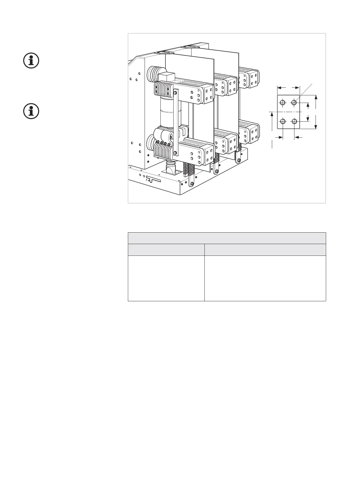
Connecting conductor bars
Important:
Aluminium conductor bars
must not be connected to
silver-plated connection
areas of the circuit-breaker. Inadmis-
sible matching of materials.
Important:
Coat contact surfaces and
comply with the specified
tightening torques (refer to
Annex).
• Take account of DIN 43 670 and
DIN 43 671 regarding the di-
mensioning for continuous cur-
rent.
• Maximum distance of the next
support point from the circuit-
breaker’s terminals in the directi-
on of the switch pole axis. 3 x
the pole center spacing of the
circuit-breaker (unless the next
supporting point is located in the
direction of the switch pole axis,
make sure that the circuit-brea-
ker pole is not exposed to higher
electrodynamic forces).
• Screw-fasten conductor bar
(take account of DIN 43 679).
• The circuit-breaker must not be
deformed by screw-fastening the
conductor bars.
Connection areas
on the circuit-breaker on the conductor bar
Silver-plated copper Copper or silver-plated copper
In case of aluminium:
use an intermediate layer of copper (thickness
0.1 mm) corresponding to the full size of the
connection area (reduction of rated normal
current by 13 %)