A transport truck (optional) is used
to rack the circuit-breaker into the
switchgear panel (Fig. 5.6). For the
design and method of operation of
the transport truck used, please refer
to the instructions for the panel in
question.
Placing the circuit-breaker on
transport truck and racking
it into the switchgear
Important:
When performing the follo-
wing assembly steps, ob-
serve and comply with the
instructions given for the panel used.
Important:
Optionally, HVX withdrawa-
ble units and panels may
be coded to match (Fig.
5.4). This is to prevent a withdrawa-
ble unit from being racked comple-
tely into the panel if the rated data
do not match.
1. Check the ratings indicated on
the nameplate between the
HVX-E and the appropriate pa-
nel.
2. Place the circuit-breaker on the
transport trolley rails.
3. Lock the circuit-breaker on the
transport trolley.
4. Couple the transport trolley to
the panel.
5. Unlock the circuit-breaker from
the transport trolley and rack the
circuit-breaker into the panel.
– HVX withdrawable units for
PIX panels must latch into
the lock rocker of the panels
(Fig. 5.4).
– HVX withdrawable units for
PIX High Current Panels are
anchored in the panel by ac-
tuation of the withdrawable
part interlock (Fig. 5.5).
6. Release the transport trolley
from the panel.
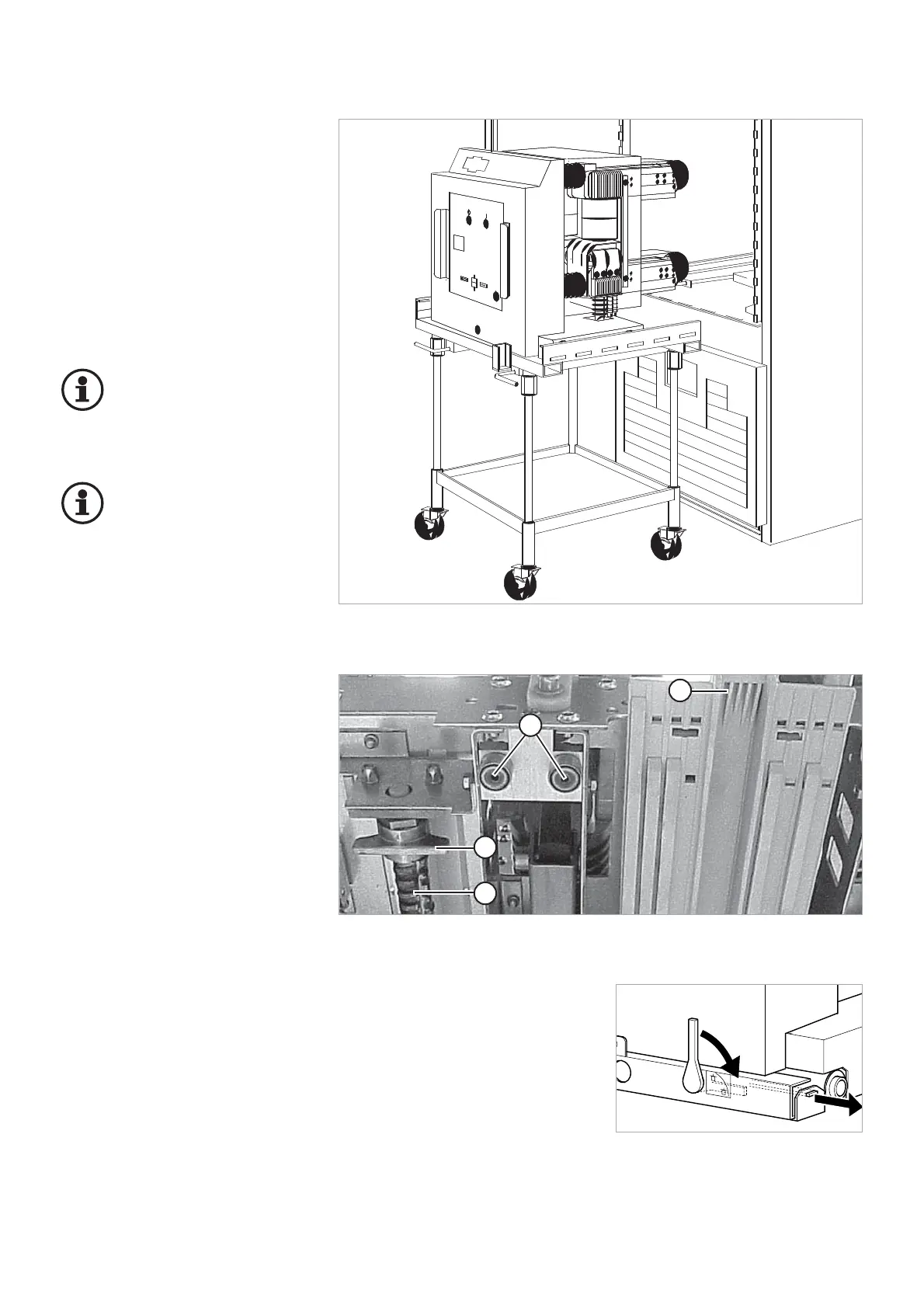
Fig. 5.3
Transport truck with HVX-E circuit-breaker in front of the panel
14
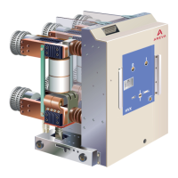
1 Spindle of the withdrawable part
2 Spindle nut of withdrawable part
(must be latched in the cell)
3 Circuit-breaker coding
4 Guide rollers