7.2 Interlocks
Warning!
You must be familiar
with these interlocks
before operating the
circuit-breaker.
19
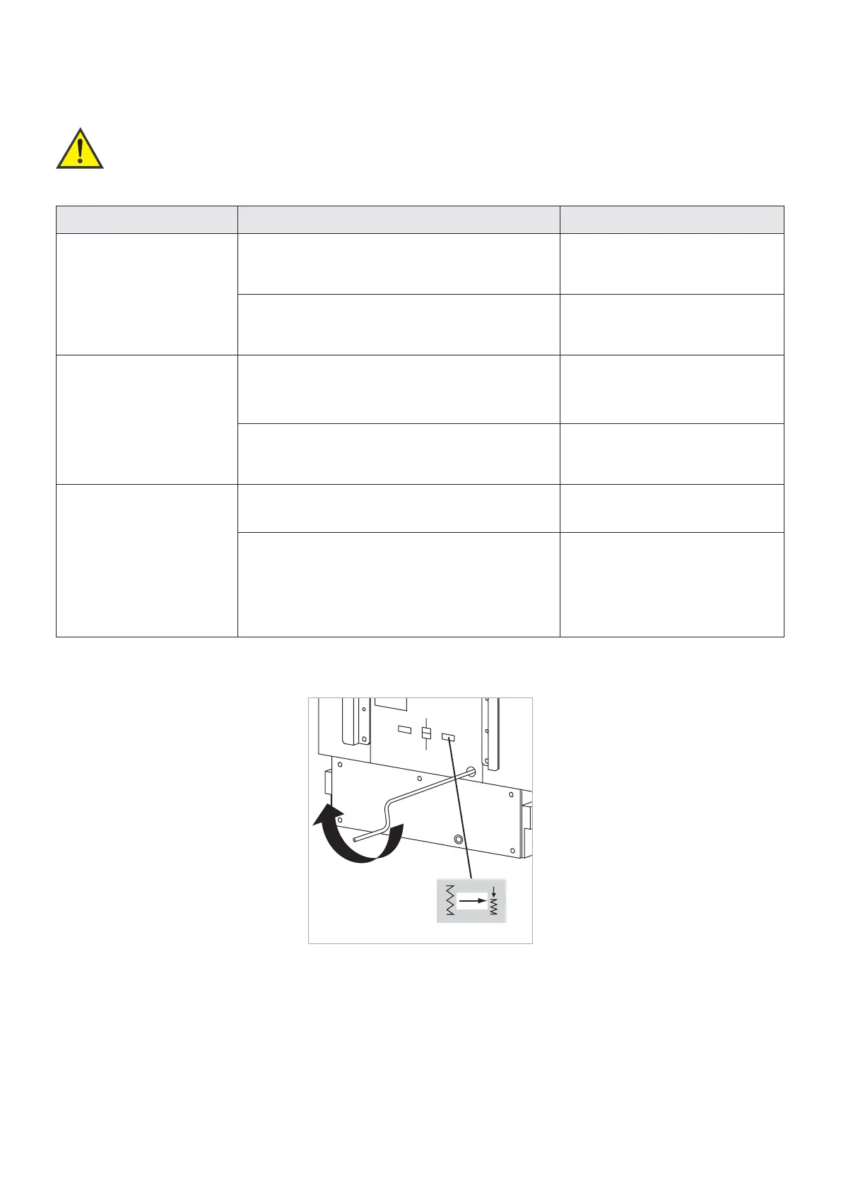
Fig. 7.5
Turn spring charging crank until the po-
sition indicator of the energy storage de-
vice indicates "charged".
Via motor
The energy storing device of motori-
zed circuit-breakers is charged auto-
matically as soon as the supply vol-
tage is applied.
Manually
Move circuit-breaker in "ready-for-
closing" position:
1. Insert crank into opening for ten-
sioning the energy storing device
(Fig. 7.5).
2. Charge the spiral spring using
the spring charging crank. As
soon as the spiral spring is char-
ged, the spring charging mecha-
nism is decoupled and the positi-
on indicator signals "charged"
(Fig. 7.5). If the motor starts du-
ring this process, this does not
constitute a risk.
3. Remove crank. The circuit-brea-
ker is ready for closing (table in
chapter 7.4, Pos. 2).
7.3 Charging the energy storing device
Mechanical interlocks
The HVX switch features basic inter-
locks to prevent operating errors.
Electrical interlocks
have been designed according to
the circuit diagram.
Interlock Function of interlock Method of operation of interlock
Between the circuit-breaker
withdrawable part and the
low-voltage connector
Switch cannot be moved into service position un-
less the low-voltage connector is inserted and lok-
ked
The opening for the moving crank
handle is locked
The low-voltage connector can only be inserted or
removed while the withdrawable part is in its dis-
connected position
The interlock between low voltage
connector and the withdrawable
part is activated
Between the circuit-breaker
withdrawable part and the
earthing switch
The withdrawable part cannot be moved to service
position in while the earthing switch of the switch-
gear panel is in "ON" position
The moving crank handle is uncou-
pled automatically
The earthing switch cannot be switched on once
the withdrawable part has left its disconnected po-
sition
The earthing switch cannot be
switched on. Do not apply force!
Between the circuit-breaker
and the withdrawable part
Circuit-breaker cannot be moved to service/discon-
nected position while it is switched on
The opening for the moving crank
handle is locked
The circuit-breaker cannot be switched on unless
– it is completely set to its service/ disconnected
position and
– the actuating crank for the withdrawable part
mechanism has been removed
The circuit-breaker cannot be swit-
ched on or off