The control lines are connected, de-
pending on design, via control con-
nectors (Fig. 5.9 and 5.10) or con-
trol lines to the terminal strips in the
drive casing. The control lines are
wired in the circuit-breaker up to the
control connector or up to the termi-
nal strip.
Single-wire conductors or strands
can be connected
• to terminal strip up to 2.5 mm
2
• in control connector up to 1.5
mm
2
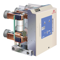
Terminal with control connector
Push the control connector onto the
64-(36-) pin right-angle plug-and
socket connector of the circuit-brea-
ker, and lock it (Fig. 5.9 und 5.10).
Important:
Connector interlock in case
of HVX-E: The control con-
nector on the panel can
only be inserted or removed while
the circuit-breaker is in disconnec-
ted position.
Connection to terminal strip
1. Remove the cover plate.
2. Connect external control lines via
the terminal strip (Fig. 5.11). The
valid wiring diagram has been en-
closed with each circuit-breaker.
If additional control lines are pla-
ced in the drive casing, leave a
sufficient distance from the mo-
vable parts of the drive.
3. After connecting the external
control line, mount the cover pla-
te.
Important:
Comply with the tightening
torques specified for
screw-fastening (refer to
Annex).
Fig. 5.11
1 Control connection on terminal strip
15
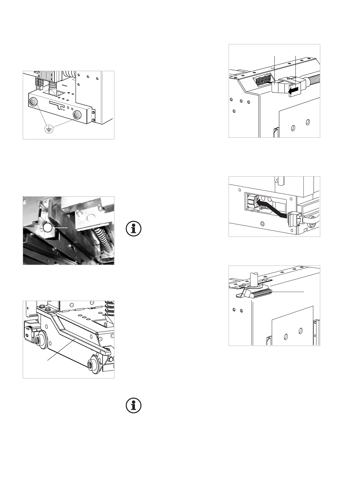
Fig. 5.6
Equipotential bonding within the cell
Optionally, the HVX-E circuit-breaker
is available with short-circuit proof
earthing (Fig. 5.7 und 5.8).
Fig. 5.9
Control connector, 64-pin
1 Insert control connector
2 Lock
Fig. 5.10
Insertion of the control connector, 36-pin
Earth terminal
The switching device potential is lin-
ked to the panel via the four wheels
of the withdrawable part (Fig. 5.6).