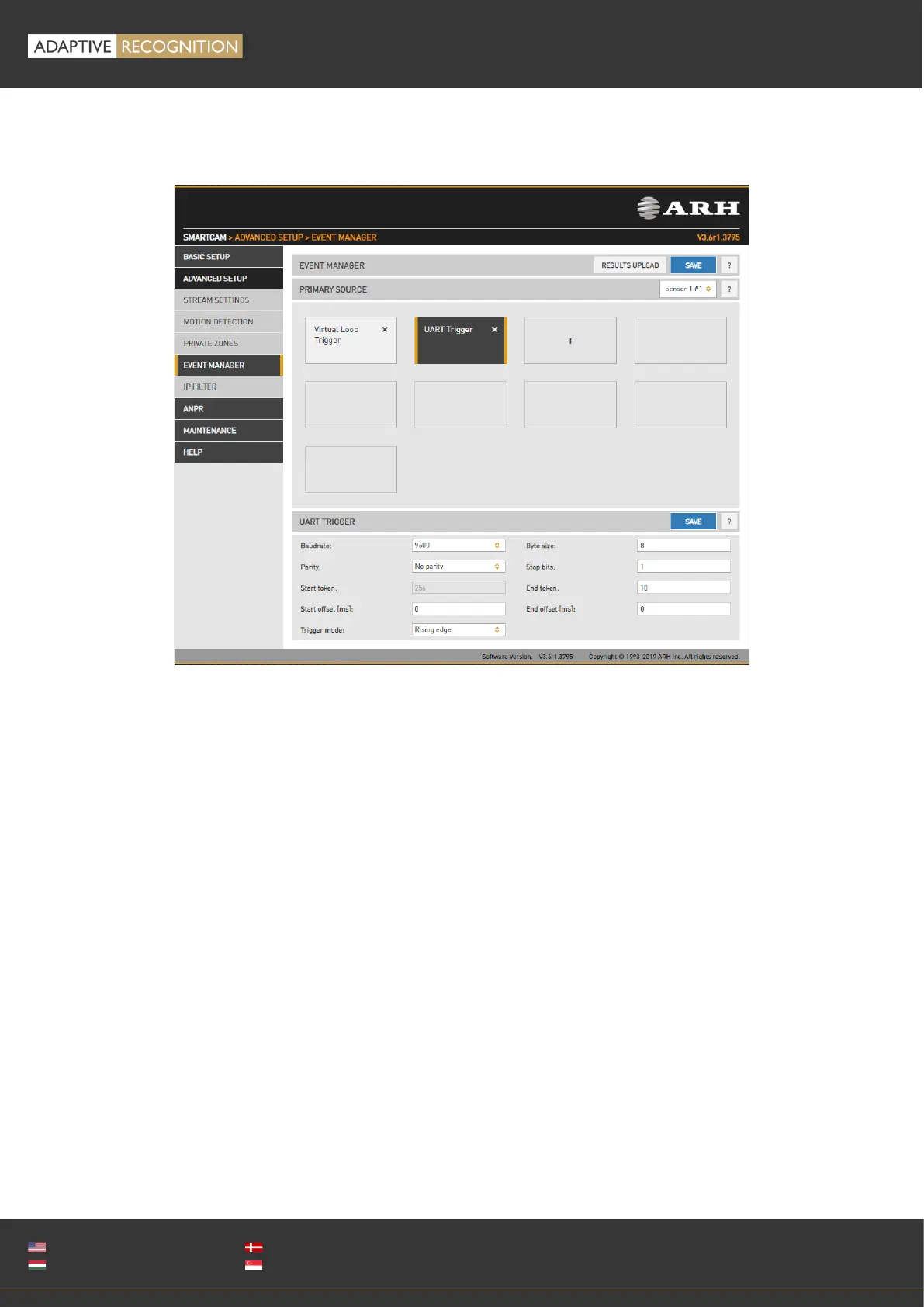
13.1.7. UART TRIGGER
The camera can be triggered through its UART port. Besides the common UART properties (Baudrate,
Byte size, number of Parity bits, and Stop bits), the communication protocol can also be specified here.
A UART trigger event starts with a Trigger Start Token (TST) byte, then maximum of 254 bytes of
trigger data may follow, and then it ends with a Trigger End Token (TET) byte.
Four trigger modes are available:
• Level: the trigger is asserted while the input is active (see below)
• Rising edge: the trigger is asserted only when TST is received
• Falling edge: the trigger is asserted only when TET is received
• Rising/Falling edge: the trigger is asserted both when TST and when TET is received
In Level Mode the trigger start timestamp will be the system time at the instant the TST arrives, plus
the Start Offset, while the trigger end timestamp will be the system time at the instant the TET arrives,
plus the End Offset. Trigger data (including the TST and TET) will be forwarded to the Event Manager.
It is possible to specify the byte value of the TST (e.g. entering 0x0A means the trigger will begin with
a '\n' byte) or check 'Start on first byte', which means, whatever byte comes first or follows the last
end token will be the trigger start token.