11
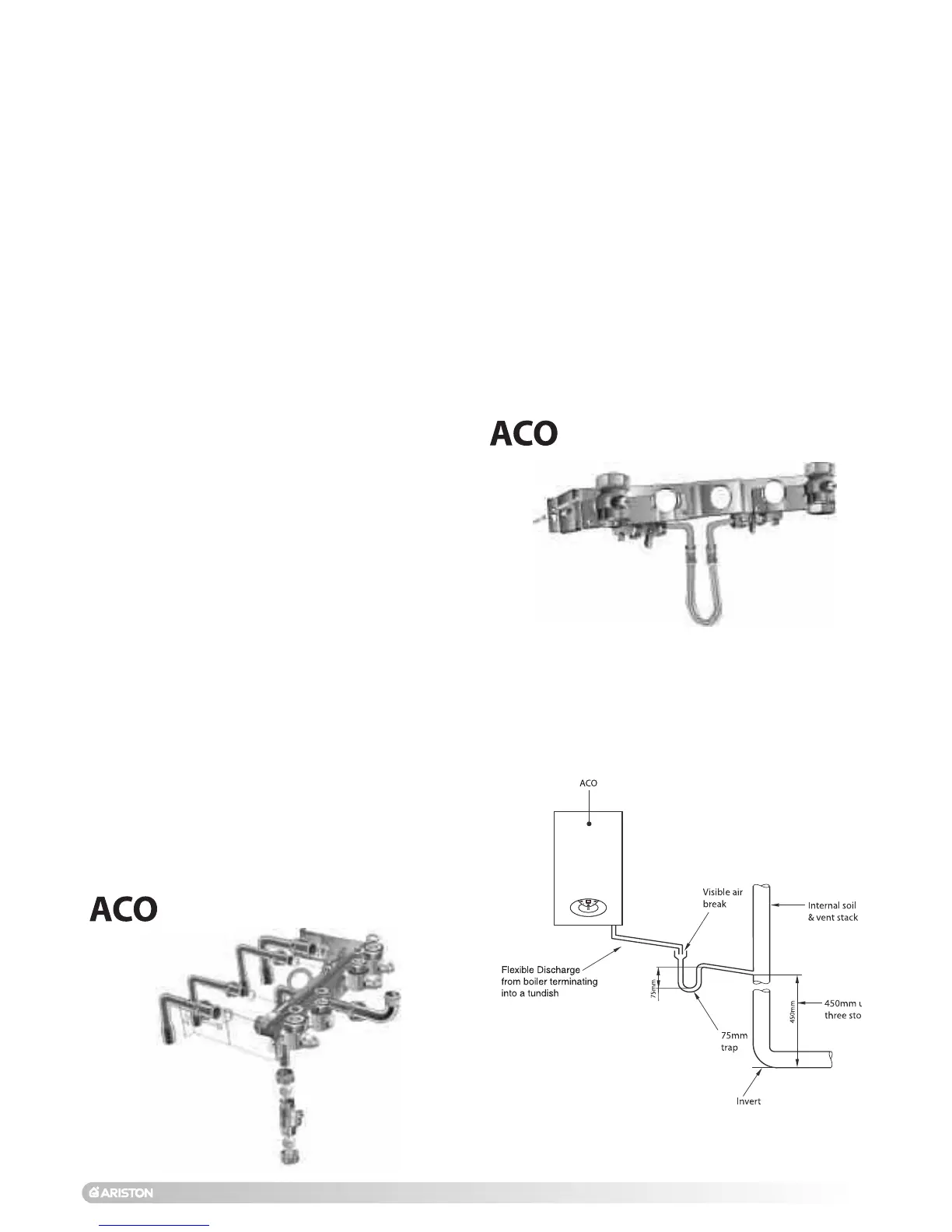
The discharge pipe must be terminated in a suitable position:
i) Connecting in to an internal soil stack (at least 450 mm
above the invert of the stack). A trap giving a water seal of
at least 75 mm must be incorporated into the pipe run,
there also must be an air break upstream of the trap.
ii) Connecting into the waste system of the building such as
a washing machine or sink trap. The connection must be
upstream of the washing machine/sink (If the connection
is down stream of the waste trap then an additional trap
giving a minimum water seal of 75 mm and an air break
must be incorporated in the pipe run, as above.
iii) Terminating into a gully, below the grid level but above the
water level.
iv) Into a soakway.
N
OTE: If any condensate pipe work is to be installed externally,
then it should be kept to a minimum and be insulated with a
waterproof insulation and have a continuous fall.
Some examples of the type of condensate drains can be
found on pages 11 and 12.
AIR RELEASE POINTS:
These must be fitted at all high points where air naturally
collects and must be sited to facilitate complete filling of the
system.
The appliance has an integral sealed expansion vessel to
accommodate the increase of water value when the system is
heated.
It can accept up to 7 l (1.5 gal) of expansion water. If the
heating circuit has an unusually high water content, calculate
the total expansion and add an additional sealed expansion
vessel with adequate capacity.
MAINS WATER FEED - CENTRAL HEATING:
There must be no direct connection to the mains water supply
even through a non-return valve, without the approval of the
Local Water Authority.
FILLING:
A method for initially filling the heating system is supplied with
the connection kit. The filling loop is connected between the
cold water inlet and the central heating flow connections, and
incorporates a non-return valve. To operate the filling loop, it
is necessary to open both quarter turn handles, once the
required pressure has been achieved, close both handles and
disconnect the hose in accordance with water byelaws and
cap off with the cap supplied. NOTE: The installer should
ensure that there are no leaks as frequent filling of the
heating system can lead to premature scaling of the main
exchanger and failure of hydraulic components.
DOMESTIC WATER
The domestic water must be in accordance with the relevant
recommendation of BS 5546:1990. Copper tubing to BS EN
1057:1996 is recommended for water carrying pipe work and
must be used for pipe work carrying drinking water, a scale
reducer should also be used to reduce the risk of scale
forming in the domestic side of the heat exchanger.
UNDER FLOOR HEATING SYSTEMS:
In the event of an under floor heating system, fit a safety
thermostat on the boiler flow (see Section 2.12). This
thermostat should be positioned at a safe distance from the
boiler to ensure the correct operation of the same. If the
thermostat is positioned too close to the boiler, the water
remaining in the boiler after domestic hot water has been
drawn will flow into the central heating system and may cause
the thermostat contact to open without there being any real
danger of the system being damaged, this would lead to a
boiler shutdown both in D.H.W. mode and C.H. mode, and the
error code
“E08” would be displayed; boiler operation resumes
automatically when the thermostat contact closes on cooling.
Should the thermostat fail to be installed as recommended, the
under floor heating system can be protected by installing a
thermostatic valve upstream from the thermostat in order to
prevent the flow of excessively hot water towards the system.
27/32 MFFI (COMBI)
27/32 RFFI (SYSTEM)
1. Internal termination of condensate drainage pipe to
internal stack
 Loading...